types of flange
Pipes are one of the components that we often encounter in industry, especially in process industry. The use of pipes in industry is very much in number so it is necessary to have a pipe connector. One of the equipment used to connect pipes is a flange.
Flange installation is the most widely used joining method after welding method. Flange is a reliable tool for connecting one pipe to another or connecting it to various equipment, valves and other components of almost any processing system. The use of flanges adds flexibility when maintaining a piping system with easier assembly and better access to system components.
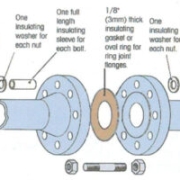
The flange connection consists of three components namely: flange, gasket, and bolt and is installed together. Special controls are required to select and apply all flange elements to obtain an acceptable leak-tight connection.

The Most Common Types and Characteristics of Flange

Threaded Flanges. Also known as threaded flanges. This model has a thread in the flange hole that fits into a male thread that fits into the pipe or fitting. Threaded connections can reduce welding in joints. Just match the thread to the pipe you want to connect.
Slip-on Flanges. Silp-on are very common and are available in a variety of sizes to accommodate systems with high flow rates. Simply match the flange to the outside diameter of the pipe you wish to connect. The installation is a bit more technical as you will need fillet welds on both sides to secure the flange to the pipe.
Lap Joint Flanges. Featuring a two-part design, Lap joints require welding from the end of the stub to the pipe or mounting using supports to create flanged joints. This design makes this type popular for use in systems with limited physical space or systems that require frequent disassembly and maintenance.
Weld Neck Flanges. Like lap joints, weld necks require welding for installation. Its performance in systems with multiple repeated bends and its reliability in high pressure and high temperature systems make it the top choice in process piping systems.
Blind Flanges. Used to terminate or isolate piping systems. The blind flange is basically a blank disc that can be bolted on. When properly installed and combined with the correct gaskets, flanges can provide a strong seal but are easily removed when needed.
In addition to the type of flange design, the type of face is another characteristic that will have a major impact on the performance and life of the flange. The type of face can determine the type of gasket and the characteristics of the seal used.
Common types of face

- Flat Face (FF)
- Raised Face (RF)
- Ring Joint Face (RTJ)
- Tongue and Groove (T&G)
- Male & Female (M&F)
The Classification of Flange Types Based On The Ability To Withstand Temperature And Pressure
It is specified using a number and a “#”, “lb”, or “class” suffix. These suffixes are interchangeable but will vary by region or vendor. The classification is as follows:
- 150#
- 300#
- 600#
- 900#
- 1500#
- 2500#
Exact pressure and temperature tolerances will vary according to the material used, flange design, and flange size. The only thing that is constant is that in all cases the pressure value decreases as the temperature increases.
The flange is below the global standard set by the American Society of Mechanical Engineers (ASME) – ASME B16.5 & B16.47. If you are trying to replace or verify an existing part, the flange must include a marker.
Standard offers a solid foundation on the basics of flange design and how to select the ideal flange for your piping system. However, with the wide variety of stainless steel flanges and other flange materials available, it is impossible to list every configuration, detail, or consideration.
Contributor: Daris Arsyada
References:
https://www.unifiedalloys.com/blog/flanges-101/ (accesed in May 15 2021)
https://blog.projectmaterials.com/flanges/flange-types-piping/#:~:text=The%20key%20types%20of%20flanges,reducer%20flange%2C%20and%20orifice%20flanges. (accesed in May 15 2021)
https://hardhatengineer.com/types-flanges-used-piping/ (accesed in May 15 2021)
https://www.pipelinedubai.com/what-is-a-flange.html (accesed in May 15 2021)

mass and energy balances
Material and energy balances are based on a conservation law which is stated generally in the form:
Change in total energy in the system = Total energy entering the system (Input) – Total energy leaving the system (Output)
Energy is the total energy of a system. The total energy of a system can be in the form of kinetic energy, potential energy, heat energy, and so on. These forms of energy can be in the form of other forms of energy so that the total energy in a system will always be the same.

Examples of Mass and Energy Equilibrium in Chemical Processes
Motor Vehicle
Chemical energy in the fuel is converted into kinetic energy in the engine. The amount of chemical energy contained in the fuel can not all turn into kinetic energy. Most of the energy that does not turn into kinetic energy will turn into other energy such as heat, friction, vibration , etc.
Energy other than kinetic that arises from the combustion process in the engine is caused by piston friction, friction in the gears on the gearbox, exhaust gases, radiator heat, wheel friction, and others. The type of unneeded energy that appears in the process is called losses.
The formula can be written as:
Total Energy Change = [Chemical Energy of the fuel (Total Input)] – [Kinetic Energy of vehicle speed (Total Output) – Losses (friction, exhaust gases, heat, etc.)]
Boiler
The simple principle of the boiler is to heat the liquid fluid that passes through the boiler using heat energy to become hot gas fluid (steam). However, heat energy cannot convert all liquid fluids into vapor completely due to losses. Some of the heat energy will be wasted due to the influence of radiation from outside the boiler, incomplete combustion of part of the volume of fuel, heat loss due to air and fuel dew, etc.
The formula can be written as:
Total Energy Change = [Heat energy in fuel (Total Input)] – [Heat energy in steam (Output) – Losses (radiation from outside the boiler, incomplete combustion, moisture in air and fuel, fuel residue, etc.)]
Cellphone
Power on the cellphone comes from a lithium battery that contains chemical energy. When the cellphone is charged, electrical energy from the socket flows into the battery and is stored in the battery into chemical energy. When a cellphone is used, the chemical energy from the battery is converted into electricity to power the screen (light energy) and speakers (sound energy). However, not all electrical energy is fully utilized by cellphone. There is some heat coming out of the cellphone or from the cellphone cable that causes our cellphones to heat up when operating. These are called losses.
The formula can be written as:
Total Energy Change: [Electrical energy in the socket (input) + Chemical energy in the battery (input)] – [Light energy on the screen (output) + Sound energy in the speaker (output)] – [Losses (heat coming from the cellphone and cable)]
So, we can formulate every activity, especially chemical processes, simply with the formula for the law of conservation of energy. This formula makes it easier for us to analyze what energies occur in a process.
Contributor: Daris Arsyada

pressure vessels in industry
A pressure vessel is a closed container designed to accommodate a high pressure gas or liquid fluid that is substantially different from the ambient pressure. Pressure vessels have wide applications in industries such as oil and gas, chemicals, petrochemicals, distillation towers, nuclear reactors, natural gas storage systems, and hot water storage tanks.
Various sizes and shapes of pressure vessels are manufactured for various purposes. In general, the type of shape that is often encountered is a long cylindrical model with two heads. Pressure vessels work at internal pressures that are higher or lower than air pressure. In addition, the operating temperature of these systems is also different.
A simple example of a pressure vessel is a pressure cooker on cooking utensils. Pressure cookers are made of high-pressure, heat-resistant metals such as stainless steel. A pressure cooker works to hold the hot steam pressure in the pan so that the steam pressure does not leak until the cooking ingredients soften completely due to heat pressure. Therefore, the pressure cooker lid is quite difficult to open because it uses a strong magnet so that the pressure does not leak.
Pressure vessels are designed to work to reach the pressure level required for certain applications. Pressure vessels can apply pressure either directly through valves, gauges, or indirectly through heat transfer. Potential pressure levels range from 15 psi to about 150,000 psi, while temperatures are often above 400 °C (750 °F). Pressure vessels can accommodate fluids ranging from 75 liters (20 gallons) to thousands of liters.
The main components of a pressure vessel:

- Shell: The main component of a pressure vessel to accommodate pressure. The shell is usually cylindrical, conical, or spherical.
- Head: Head is useful for closing the shell. Heads are generally curved. The reason for the curved shape is that it is more resistant to pressure and allows the head to be light and inexpensive.
- Nozzle: A cylindrical component that penetrates into the shell or head. Nozzle is used to install inlet and outlet pipes, install measuring instruments (altitude, temperature, pressure).
- Support: Support is used to support all pressure vessel loads so that they stand firm.
Types of pressure vessels that are often found in industry
- Process Vessel: these vessels are designed to contain and store liquids only and are used for integrated operations in petrochemical facilities, refineries, gas plants, oil and gas production facilities, and other facilities.
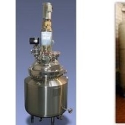
- Autoclave: These vessels are usually cylindrical in shape because their round shape is better able to withstand high pressure safely. The autoclave is designed to accommodate items that are placed inside and then the lid is tightly closed.
- High pressure vessels: the most durable vessels on the market capable of operating under the heaviest loads and providing the best resistance to corrosion, temperature and pressure. High-pressure vessels are usually made of stainless steel. These vessels are particularly suitable for use in: high speed mixers, chemical reactors and supercritical extraction systems.
- Heat Exchanger: a device that transfers heat from one medium to another. Heat exchangers are most commonly used in industrial facilities such as iron and steel, petroleum, petrochemical, gas, power generation, food, pharmaceutical, leather, textile, air conditioning, ships, and marine industries. Learn more about heat exchangers >>click here!
- Pressurized water tank: In a tank water well system, this tank generates water pressure by using compressed air to force it down above the water. Due to this pressure, water is forced out of the tank through pipes inside your home when the valve is opened.
- Vacuum tank: The vacuum tank functions to filter air or liquid through suction, outgassing, pumping, or a combination of techniques. These tanks use pressure to prevent contamination, purification and dehydration.
- Boiler: a closed pressure vessel used to heat a liquid. This heating fluid is used for cooking, power generation, central heating, water heating, and sanitation.
Selection of pressure vessel material
Materials that are often used in the design of pressure vessels are:
- Carbon steel (with carbon content below 0.25%)
- Manganese carbon steel (stronger than carbon steel)
- Low alloy steels
- High alloy steels
- Austenitic stainless steel
- Non-ferrous materials (aluminum, copper, nickel, and alloys)
In the design of pressure vessels, there are standards and codes that govern. The ASME Boiler and Pressure Vessel Code (ASME Code) is a well-known standard for pressure equipment and components worldwide and provides manufacturer certification and quality assurance. ASME sets standards for the design, materials, manufacture, inspection, testing, and operation of boilers and pressure vessels (including electric boilers, heating boilers, nuclear power plant components and transportation tanks). More than 100 countries use ASME standards and codes. The addition of the ASME certification mark to pressure equipment gives more confidence to business partners, users and governments.
Due to the complexity of pressure vessel design, analytical calculations are too complicated or even impossible. One of the most commonly used methods is to use existing standards, but sometimes these standards cannot cover in detail and comprehensively the design of pressure vessels. unique or custom vessel, so that computer modeling methods are used to calculate the structural parameters, or also known as Finite Element Analysis (FEA).
>> CLICK HERE FOR FEA SIMULATION ON PRESSURE VESSEL!
To prepare mechanical engineers to master various skills related to pressure vessels, we also provide training from trainers who are experts in their fields, both experience in the field and academics. Here are some of the training themes that we offer related to pressure vessels or vessels in general:
>>Training: Pressure vessel: calculation and inspection
>>Training: Storage tank: operation and safety
>>Training: In service pressure vessel inspection
Contributor: Daris Arsyada
aeroengineering services is a service under CV. Markom with solutions especially CFD/FEA.
References:
https://yenaengineering.nl/pressure-vessels-everything-you-need-to-know/ (accessed April 15, 2021)
https://atrinsanat.com/knowledge/pressure-vessels-components/ (accessed April 15, 2021)
https://www.wattco.com/2015/02/what-is-a-pressure-vessel/ (accessed April 15, 2021)
https://www.pressure-vessels.net/#read (accessed April 15, 2021)
https://www.gsmindustrial.com/custom-fabrication/asme-pressure-vessels-and-tanks/ (accessed April 15, 2021)
chemical reactors
Chemical reactors are undoubtedly the most important part of the chemical, biochemical, polymer and petroleum process manufacturing processes. A chemical reactor is a container that converts raw materials into chemicals that we will make as products. A wide variety of useful and important products are produced by reactions that convert reactants into products. Safety, economy, and consistent operation of chemical reactors are the main factors that make chemical reactors better.
Almost all chemical and materials industries use reactors to convert raw materials or raw materials into products. Many of the materials used for clothing, housing, cars, appliances, construction, electronics, and healthcare come from processes that utilize reactors. Reactors are important even in the food and beverage industry or agricultural product processing. The production of ammonia fertilizers for growing crops uses chemical reactors that consume hydrogen and nitrogen. Pesticides and herbicides used in crop fields are also supported by chemical reactors. Some of the drugs that form the basis of modern medicine are produced by reactor fermentation. It makes sense that modern society is now better off using chemical reactors extensively.
The reactor can operate at low temperatures (e.g. the C4 sulfuric acid alkylation reactor operates at 108 C) and at high temperatures (toluene hydrodealkylation reactor running at 6008 C). Some reactors operate in a wide variety.
Types of Chemical Reactors
Batch Reactors

A batch reactor is a vessel in which reactants are charged initially and the reaction proceeds over time. The reactants are placed into the reactor and then allowed to react, and the products are formed in the reactor. The unreacted products and reactants are then removed and the process is repeated.
Batch reactors contain ports for injecting reactants and removing products, and are equipped with a heat exchanger or stirring system. Although batch reactors generally have a constant volume, some reactors are designed to maintain a constant pressure by varying the reactor volume.
Batch reactors are used in a wide variety of applications. Usually, they are used for liquid phase reactions which require a fairly long reaction time. Batch reactors are often found in the beverage and pharmaceutical industries.
| Advantages | Disadvantages |
| High conversions can be obtained by leaving the reactants in the reactor for a long time. | High labor costs per unit of production. |
| The batch reactor jacket allows the system to change the heating or cooling power at a constant jacket heat flux. | It is difficult to maintain large-scale production. |
| Versatile, can be used to make many products in a row. | Long downtime for cleaning leads to periods of no production. |
| Good for producing a product in small batches while it is still in the testing phase. | |
| Easy to clean |
Continuous Stirred Tank Reactors (CSTR)

Continuous stirred tank reactors (CSTR) are the most basic continuous reactors used in chemical processes. (CSTR) is an open system, material is free to enter or leave the system, which operates at steady state, where conditions inside the reactor do not change over time. The reactants are continuously introduced into the reactor, while the products are continuously removed.
The CSTR consists of a tank, usually of constant volume, and a stirring system for mixing the reactants. Feed and outlet pipes are available to introduce reactants and remove products. Stirring blades, also called agitators, are used to mix the reactants.
CSTR is most commonly used in industrial processes, especially in homogeneous liquid phase flow reactions, where constant agitation is required. They can be used alone, in series, or in batteries. CSTR is also used in the pharmaceutical industry as a loop reactor.
CSTR is often used in biological processes The CSTR shown below can be used for high density animal cell culture in research or production. Vessels are used for single use only.
| Advantages | Disadvantages |
| Good temperature control that easy to maintain | Conversion of reactants to products per reactor volume is smaller than that of other flow reactors |
| Low building costs | There is a dead zone, where no mixing occurs, can develop |
| Has a large heat capacity | The reactants may escape over the limit if the outlet is placed incorrectly |
| Easily accessible reactor interior |
Plug Flow Reactors

Plug flow or tubular reactors consist of a perforated pipe or tube through which the reactants flow. The reactor consists of a cylindrical tube with an opening at each end for the reactants and products to flow. These reactors are usually operated at steady state. The reactants are continuously consumed as they flow along the reactor. The reactants will move like a flowing clump of bubbles.
Plug flow reactors may be configured as one long tube or a number of shorter tubes. Their diameters range from a few centimeters to several meters. Diameter selection is based on construction costs, pumping costs, desired residence time, and heat transfer requirements. Usually, long small diameter tubes are used with high reaction rates and large diameter tubes are used with slow reaction rates.
| Advantages | Disadvantages |
| Easy to maintain as there are no moving parts | Reactor temperature difficult to control. |
| High conversion rate per reactor volume. | Hot spots may occur within reactor when used for exothermic reactions. |
| Mechanically simple. | Difficult to control due to temperature and composition variations. |
| Unvarying product quality. | |
| Good for studying rapid reactions. | |
| Efficient use of reactor volume. | |
| Good for large capacity processes. | |
| Low pressure drops. | |
| Tubes are easy to clean. |
One of the most common methods for designing a chemical reactor process system is to use Computational Fluid Dynamics (CFD), which is a method of solving fluid mechanics equations and even chemical reactions using a computer, so that comprehensive and detailed results are obtained. >> Click here to learn more about CFD!
Contributor: Daris Arsyada
aeroengineering services is a service under CV. Markom with solutions especially CFD/FEA.
References:
https://encyclopedia.che.engin.umich.edu/Pages/Reactors/Batch/Batch.html (accessed on 14 May 2021)
https://encyclopedia.che.engin.umich.edu/Pages/Reactors/CSTR/CSTR.html (accessed on 14 May 2021)
https://encyclopedia.che.engin.umich.edu/Pages/Reactors/PFR/PFR.html (accessed on 14 May 2021)

centrifugal compressor
The compressor has the function of compressing/compressing the gas fluid into a small volume so that the temperature and pressure of the gas fluid increases. In other words, the compressor receives a mass flow of gas with a low temperature and pressure and then raises the temperature and pressure of the gas mass.
Centrifugal compressor is one of the mechanical equipment that goes into the type of rotating mechanical equipment. In general, mechanical equipment itself is divided into two types: static equipment and rotating equipment. Basically, the compressor has moving components. The use of compressors is very easy for us to encounter both in the industrial world and in our daily lives, but we do not realize it. Starting from compressors to fill air into tires, compressors in refrigeration, machinery, chemical processes, gas transmission, manufacturing and in almost every place where there is a need to compress compressible fluids.
The working principle of a centrifugal compressor is almost the same as a centrifugal pump. This compressor utilizes centrifugal force to increase the pressure and flow of fluid from the inlet to the outlet.

The rotation of the compressor impeller can produce a moment of force (torque) to the incoming liquid so that it creates a centrifugal force towards the outlet. Moment of force is an external force that causes an object to move in a circle around its axis of rotation.
In the case of a centrifugal compressor, the moment of force is the product of the cross product between the radius of the impeller and the change in the angular momentum of the impeller. Since the change in the angular momentum of the impeller is perpendicular to the radius, the direction of the moment of force will be toward the impeller (90 degrees). Keep in mind that centrifugal compressors have two impellers that rotate together at the inlet and outlet. So the total moment of the compressor force is the reduction of the moment of the outlet force with the inlet.

The total moment of force (torque) in the centrifugal compressor is formulated by Euler in the Euler’s turbine formula as:
T shaft = [r2.(m2.V2)]-[r1.(m1.V1)], because the fluid used at the outlet and inlet is the same,
m1 = m2 = m. then…
T shaft = m.[(r2.V2) – (r2.V2)]
where,
T = Total torque (Nm)
m = Mass flow rate of fluid (kg/s)
r1,r2 = inlet and outlet impeller radius (m)
V1,V2 = Linear velocity that perpendicular to the inlet and outlet impeller (m/s)
However, the calculation of centrifugal compressor analysis in the field is not that simple. The complexity of the emerging forces is very complicated if modeled into a mathematical formula. The method commonly used to analyze the flow of compressor forces is the CFD method. CFD is a method of simulating fluid flow in the design using a computer.
>> CLICK HERE TO LEARN ABOUT COMPRESSOR CENTRIFUGAL SIMULATION USING CFD METHOD !
Contributor: Daris Arsyada
aeroengineering services is a service under CV. Markom with solutions especially CFD/FEA.
References:
Cengel, Yunus A dan John M Cimbala. 2006. Fluid Mechanics: Fundamental and Application. New York: The McGraw-Hill Companies, Inc.
https://www.aiche.org/sites/default/files/cep/20130644.pdf (accessed on April 5, 2021)
https://www.airbestpractices.com/technology/air-compressors/centrifugal-air-compressor-controls-and-sizing-basics (accessed on April 5, 2021)