Komponen Poros (Shaft) Lain-lain
Poros adalah komponen paling penting pada peralatan yang bergerak memutar. Poros perlu dilindungi dengan komponen lain agar kinerjanya andal. Tidak hanya bantalan saja yang mampu melindungi poros, tetapi ada beberapa komponen lain yang dapat mendukung kinerja poros.
Setscrews
Tidak seperti baut dan sekrup tutup yang bergantung pada tegangan untuk mengembangkan kekuatan penjepit, setcrew tergantung pada kompresi untuk mengembangkan kekuatan penjepit. Ketahanan terhadap gerakan aksial atau hub relatif terhadap poros disebut daya tahan (holding power). Holding power ini merupakan hambatan gaya karena hambatan gesekan dari menyentuh bagian dari collar dan poros saat setscrew ke dalam poros.

Tabel di bawah menunjukkan nilai torsi dudukan dan holding power yang sesuai untuk setcrew seri inci. Nilai-nilai yang tercantum berlaku untuk daya tahan aksial, untuk menahan gaya dorong, dan daya tahan tangensial, untuk menahan torsi. Faktor keamanan yang khas adalah 1,5 hingga 2,0 untuk beban statis dan 4 hingga 8 untuk berbagai beban dinamis. Setscrews harus memiliki panjang sekitar setengah dari diameter poros.

Keys (Pasak) dan Pins (Susuk)
Pasak dan susuk digunakan pada poros untuk mengamankan elemen berputar, seperti roda gigi, katrol, atau roda lainnya. Pasak digunakan untuk mentransmisikan torsi dari poros ke elemen yang didukung poros. Susuk digunakan untuk penentuan posisi aksial dan untuk transfer torsi atau dorong atau keduanya.
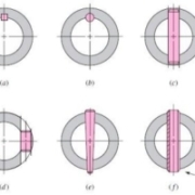
Gambar di bawah menunjukkan berbagai macam pasak dan susuk. Susuk berguna ketika beban utama adalah geser dan ketika torsi dan gaya dorong hadir. Susuk lancip berukuran sesuai dengan diameter di akhir yang besar. Diameter ujung kecil adalah d = D − 0.0208L di mana d = diameter pada ujung kecil, D = diameter pada ujung besar, dan L = panjang susuk.

Untuk aplikasi yang kurang penting, pin dowel atau pin drive dapat digunakan digunakan. Berbagai macam ini tercantum dalam katalog produsen. Pasak persegi juga tersedia dalam ukuran persegi panjang. Diameter poros menentukan ukuran standar untuk lebar, tinggi, dan kedalaman pasak. Perancang memilih panjang pasak yang sesuai untuk memikul beban puntir. Kegagalan pasak bisa dengan geser langsung, atau dengan menahan tegangan. Panjang maksimum pasak dibatasi oleh panjang hub dari elemen yang terpasang, dan umumnya tidak boleh melebihi sekitar 1,5 kali diameter poros untuk menghindari puntiran yang berlebihan dengan defleksi sudut poros. Beberapa pasak dapat digunakan untuk membawa beban yang lebih besar, biasanya berorientasi pada 90o dari satu lain. Faktor keamanan yang berlebihan harus dihindari dalam desain pasak, karena lebih diinginkan pasak gagal daripada komponen yang lebih mahal.
Cincin Penahan (Retaining Rings)
Cincin penahan sering digunakan sebagai pengganti bahu poros atau selongsong untuk memposisikan komponen secara aksial pada poros atau lubang housing. Seperti ditunjukkan pada gambar, alur dipotong di poros atau lubang untuk menerima penahan pegas. Untuk ukuran, dimensi, dan tingkat beban aksial, katalog pabrikan harus diperhatikan.

Agar cincin terpasang dengan baik di bagian bawah alur, dan penyangga beban aksial terhadap sisi alur, jari-jari di bagian bawah alur harus cukup tajam, biasanya sekitar sepersepuluh dari lebar alur. Ini menyebabkan nilai stres yang relatif tinggi faktor konsentrasi, sekitar 5 untuk lentur dan aksial, dan 3 untuk torsi. Hati-hati dalam menggunakan cincin penahan, terutama dalam lokasi dengan tegangan lentur tinggi.
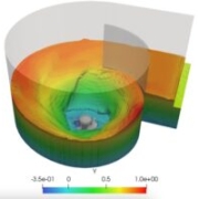
Desain komponen poros dengan FEA
Untuk mendesain struktur yang kompleks dengan detail dan interaksi beban pada komponen-komponen yang rumit seperti pada kasus komponen shaft, salah satu cara yang paling umum digunakan untuk melakukan analisis baik untuk menghitung tegangan, defleksi, fatigue, atau mungkin critical speed adalah menggunakan Finite Element Analysis (FEA). MSC Nastran adalah software FEA original pertama di dunia yang banyak sekali digunakan di berbagai industri, salah satunya untuk mendesain poros. Pelajari selengkapnya tentang MSC Nastran.
PT Tensor memberikan jasa konsultasi Finite Element Analysis (FEA) dan Computational Fluid Dynamics (CFD) untuk desain engineering. Kami juga memberikan tutorial-tutorial gratis penggunaan software nya di kanal youtube kami. Hubungi kami sekarang juga!
>> KLIK DI SINI UNTUK JASA KONSULTASI
>> YOUTUBE PT TENSOR
>> KLIK DI SINI UNTUK MEMBACA ARTIKEL LAINNYA !
Kontributor : Daris Arsyada
Sumber:
Budynas, Richard G dan J. Keith Nisbett. 2011. Shigley’s Mechanical Engineering Design: Ninth Edition. Amerika Serikat: The McGraw-Hill Companies, Inc.