
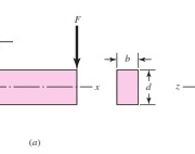
Gambar di bawah menunjukkan kantilever yang dilas ke tumpuan dengan las fillet di bagian atas dan bawah. Free body diagram balok akan menunjukkan gaya geser reaksi V dan reaksi momen M. Gaya geser menghasilkan geser primer pada las besarnya
τ’ = V/A

di mana A adalah total luas pengelasan.
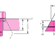
Momen M menginduksi komponen tegangan geser horizontal pada lasan. Menganggap dua lasan pada Gambar b sebagai garis, kita menemukan momen luas kedua menjadi:
Iu = bd2/2
Momen kedua dari area I, berdasarkan luas throat las, adalah
I = 0.707hIu = 0.707h (bd2/2)
Tegangan geser throat nominal sekarang ditemukan
τ” = Mc/I = (Md/2) / (0.707hbd2/2)
Momen kedua dari luas dalam Persamaan di atas didasarkan pada jarak d antara keduanya las. Jika momen ini ditemukan dengan memperlakukan kedua lasan sebagai memiliki tapak persegi panjang, jarak antara centroid throat las kira-kira (d + H). Ini akan menghasilkan sedikit lebih besar momen area kedua, dan menghasilkan level yang lebih kecil dari tegangan. Metode ini memperlakukan lasan sebagai garis tidak mengganggu konservatisme dari model.
Gaya geser vertikal (primer) dan gaya geser horizontal (sekunder) dari kemudian digabungkan sebagai vektor menjadi
τ = (τ’2 + τ”2)1/2

PT Tensor memberikan jasa konsultasi Finite Element Analysis (FEA) dan Computational Fluid Dynamics (CFD) untuk desain engineering. Kami juga memberikan tutorial-tutorial gratis penggunaan software nya di kanal youtube kami. Hubungi kami sekarang juga!
Kontributor : Daris Arsyada
Sumber:
Budynas, Richard G dan J. Keith Nisbett. 2011. Shigley’s Mechanical Engineering Design: Ninth Edition. Amerika Serikat: The McGraw-Hill Companies, Inc.
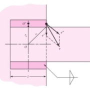
Gambar di bawah mengilustrasikan kantilever dengan panjang l yang dilas ke kolom dengan dua las fillet. Reaksi pada tumpuan kantilever selalu terdiri dari gaya geser V dan momen M. Gaya geser menghasilkan geser primer pada lasan besarnya:

τ’ = V/A
A adalah luasan yang dilas
Momen pada tumpuan menghasilkan geser sekunder atau torsi las, dan tegangan ini dirumuskan
τ” = Mr/J
di mana r adalah jarak dari pusat massa kelompok las ke titik di las b dan J adalah momen kutub kedua dari luas grup las pada pusat massa dari grup. Ketika ukuran lasan diketahui, persamaan ini dapat diselesaikan dan hasilnya digabungkan untuk mendapatkan tegangan geser maksimum. Perhatikan bahwa r biasanya adalah jarak terjauh dari pusat massa kelompok las.

Gambar di atas menunjukkan dua lasan dalam satu kelompok. Bentuk persegi panjang mewakili daerah dari hasil las. Las 1 memiliki ketebalan t1 = 0,707h1, dan las 2 memiliki ketebalan t2 = 0.707h2. Perhatikan bahwa h1 dan h2 adalah ukuran las masing-masing. Luasan kedua lasan gabungan adalah
A = A1 + A2 = t1d + t2b
Sumbu x pada Gambar di atas melewati pusat massa G1 dari lasan 1. Kedua momen luas terhadap sumbu tersebut adalah
Ix = t1d3/12
Iy = dt13/12
Jadi momen kutub kedua dari luas las 1 pada pusat massanya sendiri adalah
JG1 = Ix + Iy = (t1d3/12) + (dt13/12)
Dengan cara yang sama, momen kutub kedua dari luas las 2 terhadap pusat massanya adalah
JG2 = (bt23/12) + (t2b3/12)
Titik berat G dari grup las terletak di
x¯= (A1x1+A2x2)/A ; y¯= (A1y1+A2y2)/A
jarak r1 dan r2 dari G1 dan G2 ke G, masing-masing adalah
r1 = [(x¯- x1)2 + y¯2]1/2 dan r2 = [(y2– y¯)2+(x2– x¯)2]1/2
Sekarang, dengan menggunakan teorema sumbu paralel, kita menemukan momen kutub kedua dari luas kelompok las menjadi
J = (JG1 + A1r12) + (JG2 + A2r22)

PT Tensor memberikan jasa konsultasi Finite Element Analysis (FEA) dan Computational Fluid Dynamics (CFD) untuk desain engineering. Kami juga memberikan tutorial-tutorial gratis penggunaan software nya di kanal youtube kami. Hubungi kami sekarang juga!
Kontributor : Daris Arsyada
Sumber:
Budynas, Richard G dan J. Keith Nisbett. 2011. Shigley’s Mechanical Engineering Design: Ninth Edition. Amerika Serikat: The McGraw-Hill Companies, Inc.
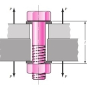
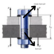
Bolt preload digunakan untuk menjepit dua pelat atau dua struktur dan membuat kunci gesekan antar member dan mengurangi efek beban bersiklus pada baut. Sehubungan dengan yang terakhir (yaitu, kelelahan baut), preload dapat membuat semua perbedaan antara struktur yang aman dan tahan lama.

Sekarang mari kita perhatikan apa yang terjadi ketika beban tarik eksternal P, seperti pada Gambar di atas diterapkan pada sambungan baut. Tentu saja, diasumsikan bahwa penjepitan gaya, yang akan kita sebut pramuat (preload) Fi telah diterapkan dengan benar dengan mengencangkan mur sebelum P diterapkan. Nomenklatur yang digunakan adalah:
Jika N baut membagi beban luar total secara merata, maka
P = Ptotal/N
Beban P adalah tegangan, dan itu menyebabkan sambungan meregang, atau memanjang, melalui jarak tertentu . Kita dapat menghubungkan perpanjangan ini dengan kekakuan dengan mengingat bahwa k adalah gaya dibagi dengan defleksi. Jadi
δ = Pb/kb dan δ = Pm/km
P = Pb + Pm , kita memiliki
Pb = KbP / (kb+km) = C P
Pm = P – Pb = (1 – C) P
dimana
C = kb / (kb+km)
disebut konstanta kekakuan sambungan. Beban baut yang dihasilkan adalah
Fb = Pb + Fi = C P + Fi ; Fm < 0
dan beban yang dihasilkan pada member yang terhubung adalah
Fm = Pm – Fi = (1-C) P – Fi ; Fm < 0
Hasil ini hanya berlaku selama beberapa beban penjepitan tetap berada di anggota.
Tabel di bawah berguna memberikan beberapa informasi tentang nilai relatif dari kekakuan yang dihadapi. Pegangan hanya berisi dua member, keduanya dari baja, dan tidak ada ring. Rasio C dan 1 C adalah koefisien P. Mereka menggambarkan proporsi beban eksternal yang diambil oleh baut dan oleh membernya masing-masing. Dalam semua kasus, member mengambil alih 80 persen dari beban eksternal. Pikirkan betapa pentingnya ini ketika ada beban kelelahan. Perhatikan juga bahwa membuat cengkeraman lebih lama menyebabkan member mengambil persentase yang lebih besar dari beban eksternal.

Metode yang umum digunakan untuk melakukan analisis baik untuk menghitung tegangan, defleksi, fatigue, atau mungkin tegangan kontak pada screw adalah menggunakan Finite Element Analysis (FEA). MSC Nastran adalah software FEA original pertama di dunia yang banyak sekali digunakan di berbagai industri, salah satunya untuk mendesain screw. Pelajari selengkapnya tentang MSC Nastran.
PT Tensor memberikan jasa konsultasi Finite Element Analysis (FEA) dan Computational Fluid Dynamics (CFD) untuk desain engineering. Kami juga memberikan tutorial-tutorial gratis penggunaan software nya di kanal youtube kami. Hubungi kami sekarang juga!
Kontributor : Daris Arsyada
Sumber:
Budynas, Richard G dan J. Keith Nisbett. 2011. Shigley’s Mechanical Engineering Design: Ninth Edition. Amerika Serikat: The McGraw-Hill Companies, Inc.
Pada bagian sebelumnya, kita menentukan kekakuan pengikat di zona yang dijepit. Pada bagian ini, kita ingin mempelajari kekakuan komponen struktur di zona terjepit. Kedua kekakuan ini harus diketahui untuk mempelajari apa yang terjadi ketika sambungan rakitan dikenai beban tarik eksternal.
Mungkin ada lebih dari dua member yang disertakan dalam pegangan pengikat. Semua member bersama-sama bertindak seperti pegas tekan secara seri, dan karenanya konstanta pegas total member adalah:
1/kmember = 1/k1 +1/k2 …… + 1/kn
Jika salah satu member adalah gasket lunak, kekakuannya relatif terhadap member lainnya biasanya sangat kecil sehingga untuk semua tujuan praktis yang lain dapat diabaikan dan hanya kekakuan gasket yang digunakan. Jika tidak ada gasket, kekakuan member agak sulit diperoleh, kecuali dengan eksperimen, karena luasan kompresi menyebar di antara kepala baut dan mur sehingga luasnya tidak seragam. Namun, ada beberapa kasus di mana luasan ini dapat ditentukan.

Gambar di atas mengilustrasikan geometri kerucut umum menggunakan sudut setengah puncak . Sebuah sudut α = 30◦ telah kita gunakan, karena sudut ini dipakai pada sebagian besar aplikasi fastener.
Mengacu pada Gambar.b, kontraksi elemen kerucut ketebalan dx mengalami gaya tekan P dapat dirumuskan menjadi
dδ = Pdx/EA
A = π (ro2 – ri2) = π {[x tan α + (D/2)]2 – (d/2)2}
dδ diintegralkan menjadi
δ = (P/π Ed tan α) ln {[(2t tan α+D-d)(D+d )] / [(2t tan α+D+d)(D-d )]}
konstanta kekakuan member adalah
k = P/δ = π Ed tan α / ln {[(2t tan α+D-d)(D+d )] / [(2t tan α+D+d)
kmember/Ed = π tan α / ln {[(2t tan α+D-d)(D+d )] / [(2t tan α+D+d) -> Kekakuan tak berdimensi
umum digunakan untuk melakukan analisis baik untuk menghitung tegangan, defleksi, fatigue, atau mungkin tegangan kontak pada joint member adalah menggunakan Finite Element Analysis (FEA). MSC Nastran adalah software FEA original pertama di dunia yang banyak sekali digunakan di berbagai industri, salah satunya untuk mendesain joint member. Pelajari selengkapnya tentang MSC Nastran.
PT Tensor memberikan jasa konsultasi Finite Element Analysis (FEA) dan Computational Fluid Dynamics (CFD) untuk desain engineering. Kami juga memberikan tutorial-tutorial gratis penggunaan software nya di kanal youtube kami. Hubungi kami sekarang juga!
Kontributor : Daris Arsyada
Sumber:
Budynas, Richard G dan J. Keith Nisbett. 2011. Shigley’s Mechanical Engineering Design: Ninth Edition. Amerika Serikat: The McGraw-Hill Companies, Inc.
http://portal.ku.edu.tr/~cbasdogan/Courses/MDesign/course_notes/Joint_Stiffness.pdf (diakses pada tanggal 9 Desember 2021)
Ketika sambungan ingin dirancang dapat dibongkar tanpa metode yang merusak dan cukup kuat untuk menahan beban tarik luar, beban momen, dan geser beban, atau kombinasinya, sambungan baut sederhana menggunakan hardened steel washer adalah solusi yang baik. Sambungan seperti itu juga bisa berbahaya kecuali jika dilakukan dengan benar, dirancang, dan dirakit oleh mekanik terlatih.
Sambungan berulir umumnya terdiri dari dua komponen, pengikat dan member. Masing-masing memiliki kekakuan yang berkontribusi pada keseluruhan kekakuan sambungan dan teridentifikasi dalam gambar di bawah ini.

Untuk mengetahui kinerja sambungan baut, perlu dilakukan perhitungan kekakuan sambungan. Itu adalah defleksi sambungan di bawah kondisi pembebanan baut. Ketika geometri sambungan baut adalah anulus dengan diameter luar kurang dari 2,5 x diameter baut, kekakuan sambungan dapat dengan mudah dihitung menggunakan k = EA/l. Ketika sambungan terdiri dari gasket non-logam atau bahan dengan modulus elastisitas rendah, komponen ini mungkin memiliki nilai kekakuan yang rendah sehingga kekakuan bagian logam sambungan akan berdampak sangat rendah pada kekakuan keseluruhan.
Kekakuan bagian baut atau sekrup di dalam zona klem umumnya akan terdiri dari dua bagian, bagian batang tidak berulir dan bagian berulir. Dengan demikian konstanta kekakuan baut setara dengan kekakuan dari dua pegas secara seri seperti pada gambar di bawah.

Kekakuan keseluruhan pengikat ditentukan dengan hubungan:
1/kbolt = 1/kt + 1/kd
atau kbolt = (ktkd) / (kt+kd)
kt = AtE/lt dan kd = AdE/ld
Substitusi persamaan kt dan kd, maka persamaan kbolt menjadi
kbolt = (AdAtE) / (Adlt+Atld)
umum digunakan untuk melakukan analisis baik untuk menghitung tegangan, defleksi, fatigue, atau mungkin tegangan kontak pada screw adalah menggunakan Finite Element Analysis (FEA). MSC Nastran adalah software FEA original pertama di dunia yang banyak sekali digunakan di berbagai industri, salah satunya untuk mendesain screw. Pelajari selengkapnya tentang MSC Nastran.
PT Tensor memberikan jasa konsultasi Finite Element Analysis (FEA) dan Computational Fluid Dynamics (CFD) untuk desain engineering. Kami juga memberikan tutorial-tutorial gratis penggunaan software nya di kanal youtube kami. Hubungi kami sekarang juga!
Kontributor : Daris Arsyada
Sumber:
Budynas, Richard G dan J. Keith Nisbett. 2011. Shigley’s Mechanical Engineering Design: Ninth Edition. Amerika Serikat: The McGraw-Hill Companies, Inc.
http://portal.ku.edu.tr/~cbasdogan/Courses/MDesign/course_notes/Joint_Stiffness.pdf (diakses pada tanggal 8 Desember 2021)
https://www.slideserve.com/odetta/chapter-8-powerpoint-ppt-presentation (diakses pada tanggal 8 Desember 2021)
Fastener (pengikat) adalah perangkat yang menahan dua atau lebih benda bersama-sama. Fastener bisa berupa baut dan mur, sekrup, paku keling, atau bahkan staples. Namun, sebagian besar pengencang digunakan dalam industri adalah pengencang berulir. Pengencang tersebut digunakan untuk menggabungkan elemen individu dengan cara yang aman dan murah yang dapat dirakit dan dibongkar sesering yang diperlukan.
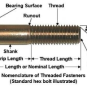
Pengikat berulir (misalnya, baut/sekrup) adalah pengencang yang sebagian memiliki beberapa bentuk dari ulir sekrup. Baut/sekrup terdiri dari shank dan kepala. Batangnya berulir, baik untuk sebagian dari panjangnya atau untuk panjang penuh dari ujung ke kepala. Baut yang lebih panjang adalah biasanya hanya berulir sebagian. Tidak perlu membuat ulir lebih lama dari yang diperlukan karena ini hanya akan membuat baut lebih mahal. Gambar berikut menunjukkan nomenklatur pengencang berulir.


Gambar di atas adalah gambar baut kepala segi enam (hexagon-head) standar. Titik konsentrasi tegangan berada di fillet, di awal ulir (runout), dan di akar ulir fillet di dalam bidang mur jika ada. Diameter muka washer sama dengan lebar di seluruh bidang segi enam. Panjang ulir baut seri inci, di mana d adalah diameter nominal, adalah

Dimensi dihitung dalam milimeter. Panjang baut yang ideal adalah yang hanya satu atau dua ulir menonjol dari mur setelah dikencangkan. Lubang baut mungkin memiliki gerinda atau tepi tajam setelah pengeboran. Hal ini bisa menggigit fillet dan meningkatkan konsentrasi tegangan. Karena itu, washer harus selalu digunakan di bawah kepala baut untuk mencegah ini. Bahannya harus dari baja hardened (yang dikeraskan) dan dimuat ke baut sehingga tepian bulat dari lubang yang dicap bertemu washer dari baut. Terkadang itu perlu menggunakan washer di bawah mur juga.


umum digunakan untuk melakukan analisis baik untuk menghitung tegangan, defleksi, fatigue, atau mungkin tegangan kontak pada screw adalah menggunakan Finite Element Analysis (FEA). MSC Nastran adalah software FEA original pertama di dunia yang banyak sekali digunakan di berbagai industri, salah satunya untuk mendesain screw. Pelajari selengkapnya tentang MSC Nastran.
PT Tensor memberikan jasa konsultasi Finite Element Analysis (FEA) dan Computational Fluid Dynamics (CFD) untuk desain engineering. Kami juga memberikan tutorial-tutorial gratis penggunaan software nya di kanal youtube kami. Hubungi kami sekarang juga!
Kontributor : Daris Arsyada
Sumber:
Budynas, Richard G dan J. Keith Nisbett. 2011. Shigley’s Mechanical Engineering Design: Ninth Edition. Amerika Serikat: The McGraw-Hill Companies, Inc.
https://practicalmaintenance.net/wp-content/uploads/Fundamentals-of-Threaded-Fasteners.pdf (diakses pada tanggal 7 Desember 2021)
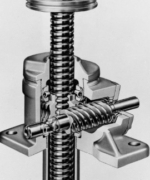
Power Screw adalah perangkat yang digunakan dalam mesin untuk mengubah gerakan sudut menjadi gerak linear, dan, biasanya untuk mentransmisikan daya. Aplikasi yang familiar dari alat ini adalah sekrup utama mesin bubut, dan sekrup pada vises, pengepres, dan dongkrak.

Gambar diatas adalah power screw ulir persegi dengan ulir tunggal memiliki rata-rata diameter dm , pitch p, sudut lead λ , dan sudut heliks ψ yang dibebani oleh gaya tekan sumbu aksial F. Untuk menaikkan beban, gaya PR bekerja ke kanan (Gambar a), dan untuk menurunkan beban, PL bekerja ke kiri (Gambar b). Gaya gesekan adalah hasil kali koefisien gesekan f dengan gaya normal N, dan bertindak untuk melawan gerakan. Sistem dalam keadaan setimbang pada aksi gaya-gaya ini. Kesetimbangan gaya untuk menaikkan beban adalah
ΣFx = PR – N sin λ – f N cos λ = 0
ΣFy = -F – f N sin λ + N cos λ = 0
Sementara untuk menurunkan beban kesetimbangan gayanya dapat dirumuskan menjadi
ΣFx = – PL – N sin λ + f N cos λ = 0
ΣFy = – F + f N sin λ + N cos λ = 0
Kita dapat menghilangkan N dari masing-masing rumus untuk mencari beban P. Beban naik dapat dirumuskan menjadi
PR = [F (sin λ + f cos λ)] / (cos λ – f sin λ) ; sedangkan untuk beban turun PL = [F (f cos λ – sin λ)] / (cos λ + f sin λ)
Selanjutnya, bagi pembilang dan penyebut persamaan ini dengan cos λ dan gunakan hubungan tan λ = l / πdm . Lalu rumus di atas menjadi
PR = {F [ (l/πdm) + f ]} / [1 – (fl/πdm)] dan PL = {F [f – (l/πdm)]} / [1 + (fl/πdm)]
Akhirnya, perhatikan bahwa torsi adalah produk dari gaya P dan jari-jari rata-rata dm/2, untuk menaikkan beban kita bisa merumuskan menjadi
TR = (Fdm/2) [(l + fπdm) / (πdm – fl)]
di mana TR adalah torsi yang diperlukan untuk dua tujuan: untuk mengatasi gesekan ulir dan untuk menaikkan beban. Torsi yang diperlukan untuk menurunkan beban adalah
TL = (Fdm/2) [(fπdm – l) / (πdm + fl)]
Jika torsi penurun negatif, beban akan menurunkan dirinya sendiri dengan menyebabkan sekrup berputar tanpa gaya eksternal. Jika torsi penurun positif, sekrup mengunci sendiri (self-locking) atau fπdm > 1. Sekarang bagi kedua ruas pertidaksamaan ini dengan dm . Karena l/πdm = tan λ, kita dapatkan f > tan λ. Relasi ini menyatakan bahwa self-locking diperoleh setiap kali koefisien gesekan ulir sama atau lebih besar dari tangen sudut ujung ulir (lead).
Efisiensi juga berguna dalam evaluasi power screw. Jika kita membiarkan f = 0 dalam Persamaan TR, kita peroleh
T0 = Fl/2π
karena gesekan ulir telah dihilangkan, torsi yang diperlukan hanya untuk menaikkan muatan. Oleh karena itu, efisiensinya adalah
e = T0/TR = Fl/2πTR

Biasanya komponen torsi ketiga harus diterapkan dalam aplikasi power screw. Ketika sekrup dimuat secara aksial, bantalan dorong atau collar (kerah ulir) harus digunakan antara komponen yang berputar dan komponen stasioner untuk memikul komponen aksial. Gambar di atas menunjukkan collar dorong khas di mana beban diasumsikan terkonsentrasi di diameter collar rata-rata dc. Jika fc adalah koefisien gesekan collar, torsi yang dibutuhkan adalah
Tc = Ffcdc/2
Untuk collar besar, torsi mungkin harus dihitung dengan cara yang mirip dengan disk clutch.

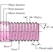
Tegangan bodi nominal pada power screw dapat dikaitkan dengan parameter ulir sebagai berikut. Tegangan geser nominal maksimum dalam torsi pada sekrup dapat dinyatakan sebagai
τ = 16T/ πd3
Tegangan aksial pada badan sekrup akibat beban F adalah
σ = F/A = 4F/ πdr2
umum digunakan untuk melakukan analisis baik untuk menghitung tegangan, defleksi, fatigue, atau mungkin tegangan kontak pada power screw adalah menggunakan Finite Element Analysis (FEA). MSC Nastran adalah software FEA original pertama di dunia yang banyak sekali digunakan di berbagai industri, salah satunya untuk mendesain power screw. Pelajari selengkapnya tentang MSC Nastran.
PT Tensor memberikan jasa konsultasi Finite Element Analysis (FEA) dan Computational Fluid Dynamics (CFD) untuk desain engineering. Kami juga memberikan tutorial-tutorial gratis penggunaan software nya di kanal youtube kami. Hubungi kami sekarang juga!
Kontributor : Daris Arsyada
Sumber:
Budynas, Richard G dan J. Keith Nisbett. 2011. Shigley’s Mechanical Engineering Design: Ninth Edition. Amerika Serikat: The McGraw-Hill Companies, Inc.
Dalam ilmu teknik, fit (kecocokan) mengacu pada jarak antara dua bagian tersambung. Pilihan fit menentukan apakah kedua bagian dapat bergerak relatif satu sama lain dalam hal kecocokan jarak bebas, atau bertindak secara keseluruhan jika fit ketat. Sementara (limit) batasan dan kesesuaian berlaku untuk semua jenis bagian tersambung, penggunaan utamanya adalah untuk mengatur ukuran poros dan lubang sambungan untuk kinerja terbaik.
Perancang bebas untuk mengadopsi geometri apa pun yang cocok untuk poros dan lubangnya. Ada dua standar untuk limit dan fit yang terkenal di dunia. Yang satu berdasarkan satuan inci dan yang lainnya berdasarkan satuan metrik. Perbedaannya terletak pada nomenklatur, definisi, dan organisasi. Tidak ada poin yang akan dilayani secara terpisah mempelajari masing-masing dari dua sistem. Versi metrik adalah yang lebih baru dari keduanya dan terorganisir.
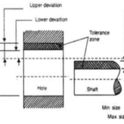
Ukuran maksimum dan minimum yang diizinkan dari ukuran komponen sebenarnya disebut limit. Limit ditetapkan dengan mengacu pada ukuran dasar dimensi itu. Batas atas (Batas tinggi) untuk dimensi itu adalah ukuran terbesar yang diizinkan dan yang terendah limit adalah ukuran terkecil yang diizinkan untuk dimensi tersebut.

Ketika dua bagian akan digabungkan, hubungan yang dihasilkan dari perbedaan antara ukuran mereka sebelum perakitan disebut fit. Fit dapat didefinisikan sebagai tingkat keketatan dan kelonggaran antara dua bagian tersambung.
Fit jenis ini berarti ada celah antara dua bagian tersambung. Mari kita lihat skema berikut representasi dari clearance fit. Diameter poros lebih kecil dari diameter lubang. Ada celah antara poros dan lubang. Oleh karena itu poros dapat dengan mudah meluncur ke dalam lubang.
Dalam clearance fit, perbedaan antara ukuran maksimum lubang dan ukuran minimum poros dikenal sebagai clearance maksimum dan perbedaan antara ukuran minimum lubang dan ukuran maksimum poros dikenal sebagai clearance minimum.
Tidak ada celah antara wajah dan akan terjadi persilangan material. Diameter poros lebih besar dari diameter lubang. Akan terjadi persilangan dua komponen tersambung akan terjadi. Oleh karena itu poros akan membutuhkan kekuatan tambahan untuk masuk ke dalam lubang.

Perbedaan antara ukuran maksimum poros dan ukuran minimum lubang ini dikenal sebagai interferensi maksimum dan perbedaan antara ukuran minimum poros dan ukuran maksimum lubang dikenal sebagai interferensi minimum.
Transition fit tidak longgar atau ketat seperti clearance fit dan interferensi fit. Toleransi zona poros dan lubang akan tumpang tindih antara interferensi dan clearance.
Sistem fit adalah sistem tunjangan standar yang sesuai dengan kisaran ukuran dasar tertentu.
Dalam sistem dasar lubang, ukuran lubang dijaga konstan dan ukuran poros divariasikan untuk mendapatkan berbagai jenis fit. Dalam sistem ini, deviasi lubang yang lebih rendah adalah nol, yaitu batas bawah lubang adalah sama dengan ukuran dasar. Batas tinggi lubang dan dua batas ukuran untuk poros adalah bervariasi untuk memberikan jenis kecocokan yang diinginkan. Sistem dasar lubang biasanya digunakan karena lebih nyaman untuk membuat lubang yang benar dengan ukuran tetap, karena bor standar, keran, reamer dan cabang dll tersedia untuk memproduksi lubang dan ukurannya tidak dapat disesuaikan. Di sisi lain, ukuran poros yang dihasilkan dengan memutar, menggiling, dll dapat dengan mudah divariasikan.

Dalam sistem basis poros, ukuran poros dijaga konstan dan kecocokan yang berbeda diperoleh dengan memvariasikan ukuran lubang. Sistem dasar poros digunakan ketika ground bar atau drawn bar tersedia. Bar ini tidak memerlukan pemesinan lebih lanjut dan kecocokan diperoleh dengan memvariasikan ukuran lubang. Dalam sistem ini, deviasi atas (deviasi fundamental) poros adalah nol, yaitu batas tinggi poros sama dengan ukuran dasar dan berbagai kecocokan diperoleh dengan memvariasikan batas bawah poros dan kedua batas lubang.

Untuk mendesain struktur yang kompleks dengan detail dan interaksi beban yang rumit seperti pada kasus shaft, salah satu cara yang paling umum digunakan untuk melakukan analisis baik untuk menghitung tegangan, defleksi, fatigue, atau mungkin critical speed adalah menggunakan Finite Element Analysis (FEA). MSC Nastran adalah software FEA original pertama di dunia yang banyak sekali digunakan di berbagai industri, salah satunya untuk mendesain poros. Pelajari selengkapnya tentang MSC Nastran.
PT Tensor memberikan jasa konsultasi Finite Element Analysis (FEA) dan Computational Fluid Dynamics (CFD) untuk desain engineering. Kami juga memberikan tutorial-tutorial gratis penggunaan software nya di kanal youtube kami. Hubungi kami sekarang juga!
Kontributor : Daris Arsyada
Sumber:
Budynas, Richard G dan J. Keith Nisbett. 2011. Shigley’s Mechanical Engineering Design: Ninth Edition. Amerika Serikat: The McGraw-Hill Companies, Inc.
https://ncet.co.in/assets/pdf/e_learning/me/ol/semIII/18MET32/MODULE%202-System%20of%20Limits,%20Fits,tolerances.pdf (diakses pada tanggal 2 Desember 2021)