mechanical properties on food
In recent years, there has been a growing interest in the physical properties of food. A number of books and reviews dealing specifically with the subject have been published. Some physical properties of food such as viscosity in fluid flow, particle size in size reduction, thermal properties in heat transfer, diffusivity in mass transfer, etc.
Mechanical Properties on Food
Mechanical properties are the properties that determine the behavior of a food material when in contact with an external force. Mechanical properties can be used for processing (eg transport, size reduction) and consumption (texture, mouthfeel). The forces acting on the material are usually expressed as stress, i.e. the intensity of the force per unit area (N/m2 or Pa). Dimensions and units of stress are similar to pressure. Very often, but not always, the response of a material to stress is deformation expressed as strain. Strain is usually expressed as a dimensionless ratio, such as elongation as a percentage of the original length. The relationship between stress and strain is the subject of a science known as rheology.
Elastic Deformation
Elastic deformation appears instantaneously when there is pressure and disappears instantly by releasing the pressure. For some materials, strain is proportional to stress, at least for moderate deformation values. The elastic deformation is defined by Hooke’s law as:
E = Stress/Strain = (F/A0)/(∆L/L0)
E = Modulus Young , Pa
F = Force, N
A0 = Initial surface area, m2
ΔL = Length increase, m
L0 = Initial length, m
Plastic Deformation
Plastic deformation does not occur as long as the stress is below a limit value known as yield stress. Plastic deformation is permanent, that is, the workpiece does not return to its original size and shape when the stress is removed.
Viscous Deformation
Deformation (flow) that occurs instantaneously with pressure and is permanent. The strain rate is proportional to the stress.
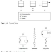
Stress types are classified according to the direction of the force in relation to the material. Normal stress is the stress that acts in a direction perpendicular to the surface of the material. Normal stresses are compressive forces if they act on the material and tensile forces if they act away from it. Shear stress acts in a parallel (tangential) direction to the surface of the material. The increase in deformation of a body under constant pressure is called creep. The decay of stress with time under constant strain is called relaxation.
Rheology Model
The stress-strain relationship in foodstuffs is usually complex. It is therefore useful to describe the actual rheological behavior of food with the help of simplifications such as drawing models. The models are constructed by connecting ideal elements (elastic, viscous, frictional, breaking, etc.) in series, parallel or a combination of both. Physical models are useful in the development of mathematical models (equations) for the description and prediction of the rheological behavior of complex foods.

Contributor: Daris Arsyada
Reference:
Berk, Zeki. 2008. Food Process Engineering and Technology. United States of America: Elsevier
types of flange
Pipes are one of the components that we often encounter in industry, especially in process industry. The use of pipes in industry is very much in number so it is necessary to have a pipe connector. One of the equipment used to connect pipes is a flange.
Flange installation is the most widely used joining method after welding method. Flange is a reliable tool for connecting one pipe to another or connecting it to various equipment, valves and other components of almost any processing system. The use of flanges adds flexibility when maintaining a piping system with easier assembly and better access to system components.
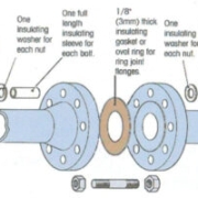
The flange connection consists of three components namely: flange, gasket, and bolt and is installed together. Special controls are required to select and apply all flange elements to obtain an acceptable leak-tight connection.

The Most Common Types and Characteristics of Flange

Threaded Flanges. Also known as threaded flanges. This model has a thread in the flange hole that fits into a male thread that fits into the pipe or fitting. Threaded connections can reduce welding in joints. Just match the thread to the pipe you want to connect.
Slip-on Flanges. Silp-on are very common and are available in a variety of sizes to accommodate systems with high flow rates. Simply match the flange to the outside diameter of the pipe you wish to connect. The installation is a bit more technical as you will need fillet welds on both sides to secure the flange to the pipe.
Lap Joint Flanges. Featuring a two-part design, Lap joints require welding from the end of the stub to the pipe or mounting using supports to create flanged joints. This design makes this type popular for use in systems with limited physical space or systems that require frequent disassembly and maintenance.
Weld Neck Flanges. Like lap joints, weld necks require welding for installation. Its performance in systems with multiple repeated bends and its reliability in high pressure and high temperature systems make it the top choice in process piping systems.
Blind Flanges. Used to terminate or isolate piping systems. The blind flange is basically a blank disc that can be bolted on. When properly installed and combined with the correct gaskets, flanges can provide a strong seal but are easily removed when needed.
In addition to the type of flange design, the type of face is another characteristic that will have a major impact on the performance and life of the flange. The type of face can determine the type of gasket and the characteristics of the seal used.
Common types of face

- Flat Face (FF)
- Raised Face (RF)
- Ring Joint Face (RTJ)
- Tongue and Groove (T&G)
- Male & Female (M&F)
The Classification of Flange Types Based On The Ability To Withstand Temperature And Pressure
It is specified using a number and a “#”, “lb”, or “class” suffix. These suffixes are interchangeable but will vary by region or vendor. The classification is as follows:
- 150#
- 300#
- 600#
- 900#
- 1500#
- 2500#
Exact pressure and temperature tolerances will vary according to the material used, flange design, and flange size. The only thing that is constant is that in all cases the pressure value decreases as the temperature increases.
The flange is below the global standard set by the American Society of Mechanical Engineers (ASME) – ASME B16.5 & B16.47. If you are trying to replace or verify an existing part, the flange must include a marker.
Standard offers a solid foundation on the basics of flange design and how to select the ideal flange for your piping system. However, with the wide variety of stainless steel flanges and other flange materials available, it is impossible to list every configuration, detail, or consideration.
Contributor: Daris Arsyada
References:
https://www.unifiedalloys.com/blog/flanges-101/ (accesed in May 15 2021)
https://blog.projectmaterials.com/flanges/flange-types-piping/#:~:text=The%20key%20types%20of%20flanges,reducer%20flange%2C%20and%20orifice%20flanges. (accesed in May 15 2021)
https://hardhatengineer.com/types-flanges-used-piping/ (accesed in May 15 2021)
https://www.pipelinedubai.com/what-is-a-flange.html (accesed in May 15 2021)

air circulation design in indoor parking space
In the current era of rapidly growing development, the construction of large buildings such as hotels, malls, offices and industries is increasing. In the construction of these facilities, there are many things that must be considered for the comfort and the safety of the users.
In this article, we will highlight the design of the indoor parking lot, which is a location that is quite risky for its users because of the accumulation of gas emissions from motorized vehicles parked in that place and the danger of a fire, considering that every parked vehicle stores fuel.
Fire incidents in indoor parking lot have occurred repeatedly and have become a special concern during the design process. When a fire starts, the air ventilation system from inside the room must properly remove smoke and gases from the parking space, and ensure the evacuation process of people inside the building without any problems, then also reduce the temperature and maintain visibility in the room to make the job of firefighters easier. To prevent poisoning, an analysis is also needed to remove the “deadzone” or area at a very low speed that has the potential to collect toxic gases in the area.
In addition to extreme conditions such as the fires described above, the presence of vehicles that are ignited when parking or in and out of parking spaces will also emit gases that are quite dangerous if accumulated in an enclosed space. These harmful gases generally include carbon monoxide (CO), nitrogen oxides (NOx and sulfur oxides (SOx).
The concentration of CO will produce the highest threat, resulting in very dangerous side effects and even death. This gas has no color but can very quickly poison humans before realizing there are indications of poisoning symptoms. CO poisoning is the most common and fatal event of air poisoning. If the air ventilation design in the space is not sufficient, poisoning and even death may occur.
The following is the concentration of CO in the air based on various international standard data:
- 200 ppm: Maximum exposure limit 15 minutes (source: NIOSH)
- 50 ppm: Maximum limit of workers exposed for eight hours (source: OSHA)
- 50 ppm: Recommended activation of mechanical ventilation in indoor parking lots (source: UMC)
- 35 ppm: Recommended < 35ppm for ambient air for one hour (source: EPA)
- 35 ppm: Maximum concentration for workers for eight hours (Source: NIOSH)
- 25 ppm: Maximum concentration for workers for eight hours (source: ACGIH)
- 25 ppm: Recommended activation of mechanical ventilation in indoor parking spaces (source: IMC)
- 9 ppm: Recommended ambient air concentration for more than eight hours (source: EPA)
ASHARAE highlights CO emission is one of the most focused on a parking lot design. For indoor parking lot, ANSI/ASHRAE Standard 62, “ventilation for acceptable indoor air quality”, recommends 9 ppm maximum for eight hours and 100-200 ppm for short periods of time. In general, the control of these gases is to use an external air supply, exhaust fan, blower and ducting.
Based on the explanation above, as a parking space designer, we must also consider good ventilation for the safety of its users. However, the design of the parking lot sometimes has to adjust the existing space so that we cannot easily analyze it based on previous experience because the data may be different. Then we have to deal with the design of the existing room with the safest solution but must still pay attention to the budget from the installation of exhaust, ducting, fans and others.
To do this, a very powerful method has been developed to analyze a room with any kind of model and configuration using a computational method with a computer, which is also known as Computational Fluid Dynamics (CFD). This method has been widely used by engineers for various fluid analysis purposes, including HVAC and of course the design of this parking space ventilation. This method is quite famous because of its capability that is not only able to predict air flow, but can also calculate air velocity, temperature, and even the concentration of certain gases at each point in 3-dimensional.
The following is an example of an analysis of a blower installation in a simple parking space:


The above simulation was made using OpenFOAM CFD software. Based on the simulation results above, we can predict which areas have high wind speeds, the “deadzone” area, and predict the concentration of gases in the room, moreover we can very easily move the location of the blower, exhaust, ducting and others with the help of a computer and predict the results of these configuration changes. Using the CFD method, we are able to understand the design problems deeper.
Boat parts
Before getting into the world of boat design or its use, it would be nice to first know the parts of the boat itself. There are some new terminology that may sound foreign in our daily life for those who are not familiar with boats. Each part of the boat has a unique name, not just front, back, right side, left side and so on.
The following describes the parts of the boat based on its orientation:

- Bow: the front of the boat
- Stern: the back of the boat
- Port: The left side of the boat as seen from the passenger facing the bow
- Starboard: The starboard side of the boat as seen from the passenger facing the bow
Based on their function, the parts of the boat can be described as follows:

- Hull: the body or part of the hull of the boat that serves to provide buoyancy and is the basic part of the boat
- Gunwales: the upper part of the hull that serves to provide extra rigidity for the hull or the installation of boat features
- Transom: the cross-section of the stern where the outboard engine is mounted
- Cleats: iron fittings that are attached to the gunwales to tighten ropes or cables when docking or leaning on the port
- Navigation Lights: Generally red and green or white, depending on the needs of each boat
The terms above are important enough to understand so that there is no confusion when designing and operating boats in the field, both for manual technical understanding and navigation.
material strength
Many materials of a structure are subjected to loads during use, such as the wings of airplanes and the shafts of automobiles. Under load conditions, it is necessary to know the characteristics of the material used so that the resulting deformation is not excessive and failure does not occur. The mechanical behavior of the material is a response to the applied load. The mechanical properties of the material can be determined by conducting tests taking into account the loading conditions, duration and environmental conditions which are arranged in such a way that they are close to their original conditions.
The mechanical behavior of the material can be determined by stress-strain testing, this test is often carried out for testing metals at room temperature. The test is carried out by applying a static load or a load that changes relatively slowly with time (quasi-static) on a cross section of the surface of the structural member. The results of these tests are engineering stress and engineering strain. Engineering stress (σ) is defined as the load (F) applied perpendicular to the cross-sectional area of the specimen (F/A0) with units of MPa or psi. Engineering strain (ε) is defined as the ratio between the increase in length due to loading (∆l) with the initial length of the specimen (l), engineering strain (ε) has no dimensions.
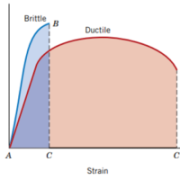
Material that is given a load will experience deformation, can experience elastic deformation or also plastic deformation. Elastic deformation is a non-permanent deformation which means that when the load is removed the material returns to its original shape, where the stress and strain are proportional to form a linear relationship. The gradient of the linear line is the modulus of elasticity (E). The modulus of elasticity is the stiffness property of the material or the resistance of the material to elastic deformation, the greater the modulus of elasticity the stiffer the material and vice versa. Plastic deformation is permanent deformation of the material, even when the load is removed. In plastic deformation, yielding phenomenon occurs, namely where there is a transition between elastic and plastic deformation. The measured stress when the yielding phenomenon occurs is called yield strength. After yielding occurs, the stress continues to increase to a maximum to continue plastic deformation. Tensile strength is the maximum stress that a material can withstand.

Ductility of a material is a material property that has the ability to undergo strain before fracture. Ductile materials usually undergo plastic deformation and reduction in cross-sectional area when fracture occurs and the necking phenomenon occurs. The fracture surface of the ductile material forms a cup and cone.
The brittleness of a material shows the properties of a material that does not undergo plastic deformation before fracture occurs. Brittle material breaks suddenly, does not experience strain, does not stretch before fracture and does not decrease in cross-sectional area before fracture. The fracture surface of a brittle material is usually flat.

Contributor: Feri Wijarnako
Onshore and offshore facilities
In learning about oil and gas, we must often hear the terms onshore and offshore. So, what do these two terms mean? Let’s discuss!
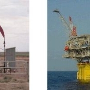
Onshore is work on land to shoreline areas for oil and gas exploration and exploitation activities. Examples of onshore work are onshore refineries and boreholes.
While offshore means work that is far from land or at sea. Offshore is an oil and gas exploration and exploitation activity carried out offshore or far from land. In offshore activities, exploration and exploitation are carried out using a platform structure installed in the middle of the ocean to support the equipment.
Onshore

Onshore production can produce more than a few tens of barrels a day. Oil and gas are produced from several million wells worldwide. For the smallest reservoirs, petroleum is collected in holding tanks and collected in tanker trucks or railcars for processing in oil refineries.
Onshore wells in oil-rich areas also have high-capacity wells producing thousands of barrels per day, connected to 1,000,000 barrels per day oil separation plants. Products are shipped from the factory by pipelines or tankers. Oil and gas production comes from many different licensees.
Recently, crude oil, tar sands and oil shale have been extracted with the latest technology and lower prices. In the extraction process, crude oil needs heating and diluent to be extracted, tar sand is extracted using steam. Oil reserves in unconventional reservoirs contain more than twice the hydrocarbons found in conventional reservoirs.
Offshore

The installation of offshore structures depends on the size and depth of the water. Some types of offshore structures that are often used are:
Shallow water complex. This structure is characterized by several independent platforms with various parts of the process and equipment connected by small bridges.
Gravity Base. A very large concrete structure is placed at the bottom. This structure accommodates all parts of the process and a large number of equipment. The structure is formed using cast concrete that is worked on the beach. Then, the structure is filled with sufficient air so that the structure floats in the sea and is carried to the middle of the sea and then planted to the seabed.
Compliant towers. Very similar to gravity base. It’s just that the shape is smaller like a narrow tower. The tower is flexible. This flexibility allows it to operate in much deeper water as it can ‘absorb’ much of the pressure exerted on it by wind and sea. The tower is used in water depths of 500 to 1000 meters.
Floating production. This structure is a structure that floats on the surface of the sea. Three examples that are often used are Floating Production, Storage and Offloading (FPSO), Tension Leg Platform (TLP) and SPAR.
FPSO is an offshore platform using large ships. The ship can rotate freely around following the direction of the wind, waves or currents. The process is placed on the ship’s deck, while the hull is used for storage and discharge of goods to the dock. It can also be used with pipeline transportation. FPSO operates at sea level at a depth of 200 -2000 meters.
The TLP consists of structures held in place by vertical tendons connected to the seabed. The structure is held in place by tensioned tendons that support the use of TLP in wide waters of depths ranging up to 2000m. The tendons are constructed with hollow high tensile strength steel tubing which brings spare buoyancy to the structure and ensures limited vertical movement.
The SPAR consists of one large tall cylinder that supports the deck (process site). However, the cylinder cannot cover the entire deck, instead it is added support material with a series of cables and beams. The large cylinder serves to stabilize the platform in the water and absorb the potential force of the storm. SPAR is used at water depths from 300 and up to 3000 meters. SPAR is not an acronym, but refers to its resemblance to a spar ship. SPARs can support dry wells, but are more commonly used in subsea wells.
Subsea production systems. Wells located on the seabed, not at sea level. Like floating production systems, petroleum is extracted on the seabed, and then it can be connected to existing production platforms or even land facilities. The wells are drilled by mobile rigs and the extracted oil and gas is transported by subsea pipelines and sent to processing facilities. Underwater systems are typically used at depths of 7,000 feet or more and have no drilling capability, only for extracting and transporting. Drilling and processing is carried out from the surface.
Contributor: Daris Arsyada
References:
Devold, Havard. 2006. Oil and Gas Production Handbook: An Introduction to Oil and Gas Production. Oslo: ABB ATPA Oil and Gas.

mass and energy balances
Material and energy balances are based on a conservation law which is stated generally in the form:
Change in total energy in the system = Total energy entering the system (Input) – Total energy leaving the system (Output)
Energy is the total energy of a system. The total energy of a system can be in the form of kinetic energy, potential energy, heat energy, and so on. These forms of energy can be in the form of other forms of energy so that the total energy in a system will always be the same.

Examples of Mass and Energy Equilibrium in Chemical Processes
Motor Vehicle
Chemical energy in the fuel is converted into kinetic energy in the engine. The amount of chemical energy contained in the fuel can not all turn into kinetic energy. Most of the energy that does not turn into kinetic energy will turn into other energy such as heat, friction, vibration , etc.
Energy other than kinetic that arises from the combustion process in the engine is caused by piston friction, friction in the gears on the gearbox, exhaust gases, radiator heat, wheel friction, and others. The type of unneeded energy that appears in the process is called losses.
The formula can be written as:
Total Energy Change = [Chemical Energy of the fuel (Total Input)] – [Kinetic Energy of vehicle speed (Total Output) – Losses (friction, exhaust gases, heat, etc.)]
Boiler
The simple principle of the boiler is to heat the liquid fluid that passes through the boiler using heat energy to become hot gas fluid (steam). However, heat energy cannot convert all liquid fluids into vapor completely due to losses. Some of the heat energy will be wasted due to the influence of radiation from outside the boiler, incomplete combustion of part of the volume of fuel, heat loss due to air and fuel dew, etc.
The formula can be written as:
Total Energy Change = [Heat energy in fuel (Total Input)] – [Heat energy in steam (Output) – Losses (radiation from outside the boiler, incomplete combustion, moisture in air and fuel, fuel residue, etc.)]
Cellphone
Power on the cellphone comes from a lithium battery that contains chemical energy. When the cellphone is charged, electrical energy from the socket flows into the battery and is stored in the battery into chemical energy. When a cellphone is used, the chemical energy from the battery is converted into electricity to power the screen (light energy) and speakers (sound energy). However, not all electrical energy is fully utilized by cellphone. There is some heat coming out of the cellphone or from the cellphone cable that causes our cellphones to heat up when operating. These are called losses.
The formula can be written as:
Total Energy Change: [Electrical energy in the socket (input) + Chemical energy in the battery (input)] – [Light energy on the screen (output) + Sound energy in the speaker (output)] – [Losses (heat coming from the cellphone and cable)]
So, we can formulate every activity, especially chemical processes, simply with the formula for the law of conservation of energy. This formula makes it easier for us to analyze what energies occur in a process.
Contributor: Daris Arsyada

coal fired boiler power plant
It is undeniable, in this modern era, the need for electricity seems to be a primary need for the running of the economy, industry and our daily lives. One type of power plant that quite dominates the supply of electricity needs in the world or in Indonesia is a steam power plant.
The use of steam power has been known for a long time and even became the forerunner of the start of the industrial revolution. The workings of this system are basically fuel in the form of coal, gas ,and others are burned to produce heat energy, then the heat energy is used to heat the water that occurs in the boiler, the hot water then changes phase into pressurized steam. height and the steam is used to turn the turbine. Sounds simple, but in fact a lot of components contained in this system. Due to its complexity, in this article we will only focus on discussing the components of a boiler with coal fuel.

Boilers for power plants are generally box-shaped with a height that extends upwards, then turns at the top and returns down facing downwards, resembling the letter “n”. The basic structure in general is the bottom to accommodate combustion, then the top and the bend are filled with pipes filled with water and steam to “take” heat from the combustion, and in the last downflow area the flue gas is reused for heat. air that will re-enter and then go to the filtering process using either a scrubber or an electrostatic dust trap.

Radiation Zone
At first, this combustion was driven using diesel fuel. When the combustion is sufficient, then coal is supplied into the combustion chamber (bottom of the boiler). The fuel inlet is usually adjacent to or surrounded by the air inlet as a source of combustion oxygen. Before entering the combustion chamber, the coal supplied by the transport ship is first put into a pulverizer or coal crusher to become small chunks so that the combustion process can occur more effectively and efficiently. In this combustion zone, the walls of this room consist of pipes containing water and steam, this wall is also called a waterwall. Because the temperature is quite high, and the fire is in the middle of the combustion chamber, the most dominant heat transfer process that occurs in this zone is radiation, so this area is often categorized as a radiation zone.
There are also various combustion patterns that are applied in this combustion chamber, for example, tangential firing which shoots fire from the corners of the room and forms a fireball, there is also a type of fuel spray that faces each other, there is even a combustion type by mixing coal using sand or coal. known as fluidized bed and there are many other variations, considering that this technology is quite mature and has been used for quite a long time.
Convection Zone
After combustion occurs in the radiation zone, naturally (and some assisted by fans) the hot air will move upwards. At the top of the radiation zone, a large number of pipes have blocked the flow of the hot gas. In these pipes there is some water and some water vapor which changes phase due to the heating of the hot gas (In the supercritical boiler type, the change of water into steam occurs spontaneously without going through a mixture of water and steam). Because the dominant heat transfer between hot gas and pipes, as well as pipes and water or steam in the pipes is convection, this zone is often referred to as the convection zone.
Superheater
In this convection zone, the tubes that face the hot gas first are called superheaters. Because in this section the water that has been perfected into steam has a very high temperature and is ready to be used to turn the turbine. This steam is also known as dry steam, dry steam or superheated steam.
Reheater
The reheater is used to take advantage of the flue gas temperature which is still hot enough after passing through the superheater. The steam from the heating of the reheater is also used to turn the turbine on the secondary stage.
Economizer
The final tubing process from the convection zone is the economizer. In this section, the hot gas that has been taken heat by the superheater and reheater still has some heat that can still be utilized. Therefore, to increase the overall efficiency, the heat from the flue gas after the reheater is used to heat the feed water system which reduces the total heat required by the system to convert the water into steam.
Air-preheater
Not yet completely cold, the flue gas that passes through the economizer is reused to heat the air that will be fed into the boiler system for combustion. This heating serves to reduce the amount of fuel required to heat the intake air to the desired temperature after combustion which in turn increases the total efficiency.
Due to the complexity of the 3D flow pattern in the boiler, the thermo-chemical interaction, as well as the interaction with the existing tubing, making the boiler difficult to analyze comprehensively using analytical methods. One method that is growing rapidly for the design, optimization and failure analysis of boiler units is to use the computational fluid dynamics (CFD) method, which is a modeling method using a computer to obtain flow parameters such as speed, pressure, temperature and so on.
>> CLICK HERE TO DESIGN A BOILER USING CFD !

water turbine
Water turbines are often used in hydroelectric power plants. The turbine has the function of changing the potential energy possessed by the water into mechanical energy (rotation) in the turbine rotor. The mechanical energy of the turbine is connected to a generator to generate electricity.
The working principle of a water turbine is the utilization of the potential energy of water to rotate the turbine blades. The water will be sprayed into the blade with high pressure so that it rotates the blade. The blade rotation will automatically rotate the turbine shaft. The rotation of the turbine shaft is forwarded to the generator shaft to generate electrical energy from the mechanical energy of the turbine.
The types of water turbines that are often used in the field are:

- Pelton Turbine: The main feature of this turbine is the blade shape like a spoon and a nozzle. With the help of the nozzle and the large capacity of the blade water, the Pelton turbine is suitable for high heads.
- Cross-flow Turbine: The main characteristic of this turbine is the shape of the runner (blades) that extends into a cylindrical shape. This turbine is suitable for low head.
- Francis Turbine: The main feature of this turbine is that its shell is shaped like a snail’s shell or shaped like a centrifugal pump. This turbine is suitable for medium-high head operation.
- Kaplan Turbine: The main feature of this turbine is the axial direction of water flow and the shape of the propeller like the propeller on a boat.
The design of a water turbine requires calculation formulas that must be considered. The calculations that are most often used as references are flow rate and head.
The flow rate is the volume of water flowing per unit second. Flow rate are generally formulated as:
Q=V.A
- Q = Flow rate (m3/s)
- V = Water flow rate (m/s)
- A = Flow cross-sectional area (m2)
Head is the flow energy per unit weight that occurs at the inlet or outlet flow. Head is expressed as a unit of distance so that the physical phenomenon of the head is the flow distance that can be reached by a fluid. Bernoulli’s equation states that the total inlet head on the turbine will be equal to the total outlet head. In general it can be written as:

However in reality, it cannot be that simple for water turbine design because usually we need some kind of prototype to test the quality of the water turbine and this method will waste a lot of money and time for testing. In modern times, there is a method called the CFD (computational Fluid Dynamics) simulation method to test fluid flow in the design of our engineering equipment using a computer.
>>> LEARN MORE ABOUT CFD SIMULATION METHOD ON WATER TURBINE !
Contributor: Daris Arsyada
References:
https://ilmuteknik.id/jenis-jenis-turbin-air-beserta-cara-kerjanya/
https://slideplayer.info/amp/11996944/