lift and drag forces on an airplane wing

To design an airplane wing or scale model, some knowledge of aerodynamics and terminology (terms) commonly used in aviation is required.

Lift and Drag Scheme. Source: https://www.cradle-cfd.com/media/column/a102

In principle, airplanes use wings to generate lift. As for producing the lift, the airplane wing utilizes two main principles, first, namely the pressure difference between the top and bottom surfaces of the wing, and secondly, the change in air velocity (momentum) due to a change in the direction of air flow.

First, to produce a pressure difference between the upper and lower surfaces of the wing, the cross-sectional shape of the wing (airfoil) is made asymmetrical between the top and bottom, the air passage above the airfoil is made farther than below the airfoil, so that with the same travel time, air passing through the top of the wing will have a higher speed than under the wing, with Bernoulli’s principle, that the higher the speed, the lower the air pressure, it may be concluded that the pressure above the wing is lower than under the wing, because the pressure above the wing is lower, then the wing will tend to “lift” upwards (This explanation based on Bernoulli’s principle is only a simplification, but can provide a sufficient qualitative description).

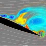
Second, the principle of velocity change (momentum). Momentum can produce a force, or according to newton’s second law that force is the rate of momentum changes. To produce this change in speed, the wing is made to have an angle relative to the direction of the air or known as the angle of attack as described in the following figure:

Angle of attack. Source: https://aerotoolbox.com/angle-of-attack/

From the picture above, it can be seen that at first the air moves straight (horizontally) towards the wing, then after reaching the rear end of the wing, the direction of the air will be leaning downwards, it can be observed that the change in the direction of velocity is downward (from straight to inclined downwards), so that to “push” the air downwards, the wings will be “pushed” by the air upwards.

It can be observed from the description above that the force caused by the pressure difference and the change in momentum is not completely directed upwards, but is slightly inclined backwards. The upward force is the lift as described above, while the backward force is the drag force or often known as the drag.

Generating lift using the second principle is indeed effective, but inefficient, because it produces a relatively large drag compared to using the pressure difference based on Bernoilli’s law (first explanation). In airplanes, lift is a combination of these two principles together.

Drag can arise due to pressure differences between the front and rear of the airfoil (form drag), changes in air velocity (momentum) or due to friction with air (skin friction drag). The difference in pressure that produces drag is also called form drag because the amount of drag is strongly influenced by the shape of the object that passes through the air, the more surface area that “blocks” the air flow, the greater the drag, then the smoother the air flow, the smaller the drag. A shape that makes the air flow change suddenly can cause the back of the object to have a low pressure, so the pressure difference gets higher (the drag gets bigger).

Effect of shape on drag. Source: http://www.pilotfriend.com/training/flight_training/aero/drag.htm

Then, drag due to change in momentum has an identical explanation to the theory of lift. The initially high velocity air is deflected downward, thereby reducing the horizontal air velocity. To “push” the air so that its speed is reduced, the wing will be “pushed” backwards, resulting in drag. Drag generated as a result of increasing lift is also called induced drag. The drag due to friction can be neglected in the design of large and high-speed aircraft because in this case the drag is dominated by form drag, but in the design of small-scale model aircraft or rides that move in water, this type of drag can be considered.

By Caesar Wiratama

Source:

https://www.cradle-cfd.com/media/column/a102

https://aerotoolbox.com/angle-of-attack/

http://www.pilotfriend.com/training/flight_training/aero/drag.htm

water content in food

Water is the most abundant substance in most foods. Classification of food is divided into three groups according to their water content (high, medium and low humidity). Fruits, vegetables, juices, raw meat, fish and dairy fall into the high humidity category. Breads, hard cheeses, and sausages are examples of medium-humidity foods, while the low-moisture groups are dehydrated vegetables, whole grains, powdered milk and dry soup mixes.

The importance of the function of water in food goes far beyond the quantity in the composition of the food. Water is essential for the good texture and appearance of fruits and vegetables. In such products, loss of water usually results in lower quality. In other hand, water, becomes an important requirement for the occurrence and support of chemical reactions and microbial growth, and prevents chemical spoilage of food.

It is now well known that the effect of water on food stability cannot be related solely to quantitative water content. For example, honey containing 23% water is very stable in storage while dehydrated potatoes will undergo rapid decay at half-high water content. To explain the effect of water, parameters that reflect the quantity and ‘effectiveness’ of water are needed. This parameter is water activity.

Water activity aw is defined as the ratio of the vapor pressure of the food to the vapor pressure of pure water at the same temperature.

aw = P/P0

P = partial pressure of water vapor of food at temperature T
P0 = equilibrium vapor pressure of pure water at temperature T. The same type of ratio also determines the relative humidity of air, RH (usually expressed as a percentage):

RH = (P’/P0)*100%

P’ = Partial pressure of water vapor in the air
If food is in equilibrium with air, then p = p’ . Therefore the water activity of the food is equal to the relative humidity of the atmosphere in equilibrium with the food. For this reason, water activity is sometimes expressed as the equilibrium relative humidity, ERH.

aw = ERH/100

Range awProduct
above 0.95Fresh fruit, vegetables, milk, meat, fish
0.90-0.95semi-hard cheese, anchovies, bread
0.85-0.90hard cheese, sausage, butter
0.80-0.85fruit juice, jelly, wet pet food
0.70-0.80jam, dry cheese, legumes, plums
0.50-0.70raisins, honey, seeds
0.40-0.50almond nut
0.20-0.40Non-fat milk powder
<0.2biscuits, roasted ground coffee, sugar

Typical water activity in food

The main mechanisms that contribute to the decrease in water vapor pressure in food are solvent-solute interactions, binding of water molecules to the poles of polymeric substances (e.g. polysaccharides and proteins), adsorption of water on the solid surface matrix and capillary forces. In high-moisture foods, such as fruit juices, depression can be attributed entirely to water-solute interactions. If the food is considered an ‘ideal solution’, this water vapor pressure applies Raoult’s law:

P = XwP0

Where Xw is the water content (in mole fraction) of the food. Therefore the water activity of an ideal aqueous solution is equal to the molar concentration of water Xw. The water activity of foods with high humidity (with an aw of 0.9 or higher) can be calculated quite accurately by this method.

Contributor: Daris Arsyada

By Caesar Wiratama

References:

Berk, Zeki. 2008. Food Process Engineering and Technology. United States of America: Elsevier

pressure vessels in industry

A pressure vessel is a closed container designed to accommodate a high pressure gas or liquid fluid that is substantially different from the ambient pressure. Pressure vessels have wide applications in industries such as oil and gas, chemicals, petrochemicals, distillation towers, nuclear reactors, natural gas storage systems, and hot water storage tanks.

Various sizes and shapes of pressure vessels are manufactured for various purposes. In general, the type of shape that is often encountered is a long cylindrical model with two heads. Pressure vessels work at internal pressures that are higher or lower than air pressure. In addition, the operating temperature of these systems is also different.

A simple example of a pressure vessel is a pressure cooker on cooking utensils. Pressure cookers are made of high-pressure, heat-resistant metals such as stainless steel. A pressure cooker works to hold the hot steam pressure in the pan so that the steam pressure does not leak until the cooking ingredients soften completely due to heat pressure. Therefore, the pressure cooker lid is quite difficult to open because it uses a strong magnet so that the pressure does not leak.

Pressure vessels are designed to work to reach the pressure level required for certain applications. Pressure vessels can apply pressure either directly through valves, gauges, or indirectly through heat transfer. Potential pressure levels range from 15 psi to about 150,000 psi, while temperatures are often above 400 °C (750 °F). Pressure vessels can accommodate fluids ranging from 75 liters (20 gallons) to thousands of liters.

The main components of a pressure vessel:

Pressure vessel components. Source: atrinsanat.com
  • Shell: The main component of a pressure vessel to accommodate pressure. The shell is usually cylindrical, conical, or spherical.
  • Head: Head is useful for closing the shell. Heads are generally curved. The reason for the curved shape is that it is more resistant to pressure and allows the head to be light and inexpensive.
  • Nozzle: A cylindrical component that penetrates into the shell or head. Nozzle is used to install inlet and outlet pipes, install measuring instruments (altitude, temperature, pressure).
  • Support: Support is used to support all pressure vessel loads so that they stand firm.

Types of pressure vessels that are often found in industry

  • Process Vessel: these vessels are designed to contain and store liquids only and are used for integrated operations in petrochemical facilities, refineries, gas plants, oil and gas production facilities, and other facilities.
  • Autoclave: These vessels are usually cylindrical in shape because their round shape is better able to withstand high pressure safely. The autoclave is designed to accommodate items that are placed inside and then the lid is tightly closed.
  • High pressure vessels: the most durable vessels on the market capable of operating under the heaviest loads and providing the best resistance to corrosion, temperature and pressure. High-pressure vessels are usually made of stainless steel. These vessels are particularly suitable for use in: high speed mixers, chemical reactors and supercritical extraction systems.
  • Heat Exchanger: a device that transfers heat from one medium to another. Heat exchangers are most commonly used in industrial facilities such as iron and steel, petroleum, petrochemical, gas, power generation, food, pharmaceutical, leather, textile, air conditioning, ships, and marine industries. Learn more about heat exchangers >>click here!
  • Pressurized water tank: In a tank water well system, this tank generates water pressure by using compressed air to force it down above the water. Due to this pressure, water is forced out of the tank through pipes inside your home when the valve is opened.
  • Vacuum tank: The vacuum tank functions to filter air or liquid through suction, outgassing, pumping, or a combination of techniques. These tanks use pressure to prevent contamination, purification and dehydration.
  • Boiler: a closed pressure vessel used to heat a liquid. This heating fluid is used for cooking, power generation, central heating, water heating, and sanitation.

Selection of pressure vessel material

Materials that are often used in the design of pressure vessels are:

  • Carbon steel (with carbon content below 0.25%)
  • Manganese carbon steel (stronger than carbon steel)
  • Low alloy steels
  • High alloy steels
  • Austenitic stainless steel
  • Non-ferrous materials (aluminum, copper, nickel, and alloys)

In the design of pressure vessels, there are standards and codes that govern. The ASME Boiler and Pressure Vessel Code (ASME Code) is a well-known standard for pressure equipment and components worldwide and provides manufacturer certification and quality assurance. ASME sets standards for the design, materials, manufacture, inspection, testing, and operation of boilers and pressure vessels (including electric boilers, heating boilers, nuclear power plant components and transportation tanks). More than 100 countries use ASME standards and codes. The addition of the ASME certification mark to pressure equipment gives more confidence to business partners, users and governments.

Due to the complexity of pressure vessel design, analytical calculations are too complicated or even impossible. One of the most commonly used methods is to use existing standards, but sometimes these standards cannot cover in detail and comprehensively the design of pressure vessels. unique or custom vessel, so that computer modeling methods are used to calculate the structural parameters, or also known as Finite Element Analysis (FEA).

>> CLICK HERE FOR FEA SIMULATION ON PRESSURE VESSEL!

To prepare mechanical engineers to master various skills related to pressure vessels, we also provide training from trainers who are experts in their fields, both experience in the field and academics. Here are some of the training themes that we offer related to pressure vessels or vessels in general:

>>Training: Pressure vessel: calculation and inspection

>>Training: Storage tank: operation and safety

>>Training: In service pressure vessel inspection

Contributor: Daris Arsyada

By Caesar Wiratama

aeroengineering services is a service under CV. Markom with solutions especially CFD/FEA.

References:

https://yenaengineering.nl/pressure-vessels-everything-you-need-to-know/ (accessed April 15, 2021)

https://atrinsanat.com/knowledge/pressure-vessels-components/ (accessed April 15, 2021)

https://www.wattco.com/2015/02/what-is-a-pressure-vessel/ (accessed April 15, 2021)

https://www.pressure-vessels.net/#read (accessed April 15, 2021)

https://www.gsmindustrial.com/custom-fabrication/asme-pressure-vessels-and-tanks/ (accessed April 15, 2021)

BUILDING VENTILATION DESIGN

Nowadays, along with the emergence of the issue of the energy crisis, waste accumulation, lack of water and other environmental issues related to the growth of the human population who continues to build infrastructure for homes, factories, offices and others, the concept of green building is also growing.

Green building is a building that combines environmentally friendly products, starting from natural materials, concepts to save energy and water, or using recycled materials to utilize materials that cannot be decomposed or wasted. Design considerations or products that contribute to safety, and environmental health are also an important part of green building, one of the important considerations is the design of a good Heating Ventilation and Air-conditioner (HVAC).

Since the building will basically be inhabited by humans, and humans need good air to breathe, the design of good ventilation is quite essential. There is special emphasis on Indoor Environmental Quality (IEQ) on green building which must consider humidity control, air filtration, contamination control and of course ventilation.

There are various ways to get good ventilation in a building, while in green buildings the methods that are often used are natural ventilation, energy recovery ventilation, whole-house fans, energy-saving exhaust fans, and a combination of these methods to get the sufficient amount of ventilation. Whatever method is used; a green building designer must ensure that the combination of methods or equipment supports each other.

Nowadays, green building attracts the attention of many parties, because the concept is profitable in terms of energy use and sustainable for the environment globally, as well as in terms of business and marketing for building developers. Basically, ventilation systems in buildings in general and green buildings do not have a significant difference, but in the design of green buildings we expect the use of energy to be minimal.

To achieve adequate ventilation, sometimes passive airflow is insufficient and mechanical equipment such as fans or the use of an Energy Recovery Ventilator (EVR) system is required. Some of the standards that can be applied to mechanical whole-house ventilation are to meet ASHARAE 62.2 requirements with the following details:

  • Whole-house mechanical ventilation system and controls installed to supply a certain rate of outside air (62.2 section 4), including ventilation limits at 62.2 section 4.5 (e.g. maximum 7.5 cfm/100 sq.ft) for “warm-humid” climates as defined by the IECC.
  • Air transfer (used air in other rooms/ducting) should not be used.
  • The air inlet is located at least 10 feet from the source of the contaminant.
  • Air flow must be tested first to meet the design criteria of the manufacturer: for example, to check the air mass flow rate value is in accordance with the specifications.

Then, according to ASHARAE 62.2 section 5, local exhaust ventilation that leads out of the room must be installed in each bathroom and kitchen.

Regardless of the method used for ventilation, the important thing that must be considered for green building designers is to ensure that the methods used support each other and do not reduce each other’s performance, for example installing an exhaust fan with an air flow rate which after being tested has lower flow rate than the specification, this may happen if there is intervention from other tools installed in inappropriate locations.

Or maybe the installation of air inlets from blowers or fans whose flow is not evenly distributed throughout the room: there are areas with high local air velocity but there are also areas that are not touched by air circulation at all and many more.

To overcome these problems, analytical/manual calculations are sometimes not possible due to special building plans or new building types and there has never been a previous reference, one of the best and rapidly developing alternatives currently being used is to use computer computing methods to model the air flow, or temperature distribution in the room, or also known as Computational Fluid Dynamics (CFD).

Using the CFD method, we can model unlimited room models like whatever we want and the locations of tools such as fans, exhausts, inlets, blowers and others, even this method can also model natural convection flows by taking into account the buoyancy that occurs due to differences in density due to differences in air temperature.

Moreover, if needed, we can model the exterior of the building being blown by the wind to see how much air is entering the building and air passing through the building just like that.

The pictures below are examples of a CFD analysis on a church building to see the characteristics of the air flow when passing through the building under various conditions (doors open/closed, windows open/closed, people inside/empty and so on).

simulation of air flow around the building
simulated airflow entering the building
Simulation of indoor air flow with forced convection system
Vector plot of velocity in the ventilation inlet system

The above simulations were made using openFOAM CFD software. Using the CFD software, we are able to get a more in-depth and specific insight into the designs we make.

>> CLICK HERE TO LEARN ON VENTILATION DESIGN USING CFD!

For those of you mechanical engineers who are improving their skills in the HVAC field, we also provide solutions, namely training on topics about HVAC with trainers who are very experienced in their fields to improve your skills and competencies as a professional engineer. Here are some training topics related to HVAC topics:

>>Training: Air conditioning and refrigeration: operation, installation and maintenance

>>Training: HVAC system commissioning

By Caesar Wiratama

aeroengineering services is a service under CV. Markom with solutions especially CFD/FEA.

resistances on the hull of the ship

The design of the hull of ships and boats is quite a challenging job because there are quite a number of variables that should be taken into account. One of the calculations that is quite important in hull design is resistance, because the magnitude of the resistance determines the effectiveness of the hull design that we make, more than that, the resistance will also affect the amount of engine power needed to move the ship. The first thing we need to understand in calculating this drag is the interaction of the hull with the propulsion system.

The ship’s propulsion system interacts with the ship’s hull and changes the flow pattern and resistance value of the ship itself. To facilitate the analysis of the drag on the hull, sometimes the propeller and hull analyzers are separated during laboratory testing, and even the rudder is sometimes separated during testing. The method that is currently developing is using a computer, namely the Computational Fluid dynamics (CFD) method. CFD method may be used for comprehensive analysis with the help of computer modeling.

Free surface wave modeling around the hull with openFOAM CFD

The calculation of the power required by the ship can be calculated using the general power equation:

POWER = FORCE * SPEED

Force is the drag or resistance of the ship and speed is the speed of the ship itself. From the above equation it can be shown that the resistance of the ship is directly proportional to the power required to move the ship.

The power required to push the ship forward is certainly less than the power generated by the thrust generated by the propeller, so the power generated by the propeller can be calculated using the following relationship:

THRUST POWER = THRUST * ADVANCE SPEED

Thrust is the force generated by the propeller that may the ship moving forward, while the advance speed is the velocity of the water flow before it reaches the propeller. On the propeller tested without the hull, this advance speed can be calculated easily based on the flow velocity. Meanwhile, in the presence of a hull, this velocity changes due to the interaction of the flow with the hull.

Thrust resulting from the propulsion test is higher than the hull resistance produced without a propeller, so calculations for additional resistance are needed with the following factors:

  1. The propeller adds flow velocity to the rear of the hull which increases frictional resistance.
  2. The propeller reduces the pressure on the back of the hull due to the high velocity (Bernoulli’s law).

The advance speed of the propeller is generally slower than the wake speed of the ship. The wake speed is divided into three components:

  1. Friction wake: due to viscosity, the relative speed of the vessel is slowed at the boundary layer, resulting in flow separation and resulting in a wake.
  2. Potential wake: Velocity at the stern is similar to that of the bow with a lower velocity at the stagnation point producing a wake flow.
  3. Wave wake: the wave system on the ship changes locally due to the orbital velocity below the wave, the wave fragment due to the propeller also increases the wake.

Wave wake is only significant for Froude number, Fn > 0.3. Wake on the towing tank test model is larger than the full scale boundary layer, then the flow separation is also relatively large and a correction factor is needed. The wake behind the ship without the propeller is called the nominal wake, while the wake behind the propeller is called the effective wake. The flow around the propeller accelerates the flow rate by about 5-20%.

Based on the above relationships, it can be calculated the ratio of effective power to thrust power which represents the efficiency of the hull design that we make, this parameter is also called hull efficiency which is mathematically written as follows:

HULL EFFICIENCY = EFFECTIVE POWER/THRUST POWER 

= (RESISTANCE*HULL SPEED) / (THRUST*ADVANCE SPEED)

Then, based on the relationship between torque and rpm of the propeller, the power generated by the propeller can be calculated by the following equation:

POWER = 2.pi * RPM * TORQUE

Power at the above equation is less than the brake power, or the power generated by the propeller turning engine.

FACTORS CAUSED RESISTANCE ON THE HULL

After discussing the interaction between the hull and the propeller, then we will discuss the sources of ship resistance in general. In general, the causes of ship resistance are often separated into each category as follows:

1. Friction resistance: friction between the walls of the boat and the water causes a velocity difference between the speed on the wall of the boat and the speed of the water around the boat. The difference in velocity results in the emergence of a boundary layer that restrains the ship’s motion.

CFD simulation of frictional resistance in the hull using openFOAM

2. Viscous pressure resistance: the shape of the ship moving forward causes changes in the flow pattern around it, especially at the fore and aft. At the front there is stagnation pressure due to “stopping” the flow due to hitting the front of the ship, this pushes the ship with a force towards the rear. The wake at the rear of the ship produces an area of ​​low pressure, this sucks the ship with a backward force. Ships with an elongated shape tend to have low resistance, but greater friction resistance, and vice versa.

CFD simulation of hull pressure using openFOAM

3. Wave resistance: the energy in the waves is generated by the motion of the ship which produces drag. This wave is divided into two primary and secondary waves.

(1) primary wave system: The flow at the fore and aft of the ship is lower than the middle, and the highest at the stagnation pressure at the fore. The pressure difference produces a primary wave pattern whose shape depends on the velocity, but the location of the maximum, minimum and zero height of the wave is not affected by the velocity. The wave height is directly proportional to the square of the velocity.

(2) Secondary wave system: On the free surface, waves are formed and flow towards the back of the ship. The wave pattern consists of transverse and divergent waves. In deep water, the wave forms an angle of 19.5 deg , the angle is not affected by the shape of the ship. In shallow water, the angle is 90 deg and gets smaller and smaller.

The design, especially the calculation of the resistance on the ship, is very complex if it is carried out using analytical calculations (pure mathematics), so experiments are needed to calculate it more easily, for example using a towing tank. However, the testing costs and time for prototyping are relatively high; so that the current design trend for ship hulls is to use computational fluid dynamics (CFD) using computational methods.

>>CLICK HERE FOR CFD SIMULATION ON SHIP HULL!

By Caesar Wiratama

aeroengineering services is a service under CV. Markom with solutions especially CFD/FEA.

material fatigue

Fatigue is a material damage caused by repeated loading for a long time. If a metal is subjected to repeated loads (stress or strain), the metal will fracture. Damage due to repeated loads is called fatigue failures, generally this occurs after the use of the material for a long time. The damage occurs without warning, suddenly, and completely. More than 90% of the causes of mechanical failure are caused by fatigue fracture.

Phases in Fatigue Fracture:

  1. Initiation crack
  2. Crack propagation
  3. Fracture failure
Fatigue fracture phases. Source: PT. Hesa Laras Brilliant

In general, the process of crack initiation occurs on the surface of the weak material or areas where there is a concentration of stress on the surface, such as scratches, notches, holes, etc., due to repeated loading. Furthermore, the beginning of these cracks develops into microcracks, the propagation or combination of these microcracks then forms macrocracks which will lead to failure. After that, the material will experience a final fracture, because the material has undergone a stress and strain cycle that results in permanent damage.

Basically, fatigue failure begins with the occurrence of cracks on the surface of the material. It proves that fatigue properties are very sensitive to surface conditions, which are influenced by several factors, including surface roughness, changes in surface properties, and surface residual stress. Therefore, the endurance limit is highly depends on the quality of the surface finish. Surface treatment may change the surface condition and residual stress on the surface. Surface treatment that produces compressive residual stress will result in increased fatigue resistance, while surface treatment that produces tensile residual stress will decrease its fatigue resistance.

At the surface of the material the highest concentration of compressive or tensile stress occurs. If the surface conditions are receiving tensile stresses, the residual compressive stress on the surface will result in a greater resultant compressive stress. The compressive stress will inhibit the initiation of crack, so that the fatigue resistance will increase, and the opposite will happen if there is residual tensile stress on the surface. The initial location of cracks in components or metals that are subjected to dynamic or cyclic loading is at the point of the region that has the minimum strength and or the point of the region experiencing the maximum stress.

Failure of components or structures can be divided into two main categories. First, quasi-static failure (failure that does not depend on time, and resistance to failure is expressed by strength). Second, time-dependent failure (resistance to failure is expressed by age or life time). Metal fatigue (fatigue fracture) is included in the time-dependent failure.

Factors Affecting Metal Fatigue

  1. Loading
    • Load type: uniaxial, bending, torsion
    • Load pattern: periodic, random
    • Load amount
    • Load cycle frequency
  2. Material condition (grain size, strength, solid solution reinforcement, second phase reinforcement, strain reinforcement, microstructure, surface finish), component size).
  3. Working process (casting process, forming process, welding process, machining process, heat treatment process)
  4. Operating temperature
  5. Environmental conditions
Fatigue cracked surface. Source: Ewing & Humfrey (1903)

Contributor: Feri Wijarnako

By Caesar Wiratama

aeroengineering services is a service under CV. Markom with solutions especially CFD/FEA.

main processes of oil and gas production

The oil and gas industry is one of the industries that demands highly engineered and varied processes. In this article, we will discuss some of the most common processes encountered in the oil and gas production process.

An Examples of the production processes in oil and gas. Source: Oil and Gas Production Handbook (2006)

Wellheads

The wellhead is above the actual oil or gas well leading to the reservoir. The wellhead can also be an injection well, used to inject water or gas back into reservoir to maintain pressure and level to maximize production. This process consists of reinforcing the wellbore with a casing, evaluating the formation pressure and temperature, and then installing the appropriate equipment to ensure an efficient flow of natural gas out of the well. Well flow is controlled by a choking device.

Manifolds/gathering 

Onshore – The well flow is brought to the main production facility via a pipeline collection network and manifold system. The aim is to regulate production so that production levels increase, utilize the reservoir as well as possible, adjust the composition of the well flow (gas, oil, etc.) appropriately.

Offshore – Dry completion of the well in the central main field feeds directly to the production manifold, while the outer wellhead tower and subsea installation feed via multiphase pipelines back to the production rungs. A riser is a system that allows the piping to “go up” to the superstructure. To float a structure, this involves taking the weight of the structure and moving it. For heavy crude oil, diluents and heating may be required to reduce viscosity and facilitate flow rates.

Separation

Some wells have pure gas production which can be taken directly to gas treatment and/or compression. More often, wells consist of a combination of gas, oil and water and various contaminants must be separated and processed. The production of separators comes in various shapes and designs.

Gas Compression

The gas from the pure gas well has sufficient pressure to be supplied directly to the pipeline transport system. The gas from the separator generally loses so much pressure that it must be compressed to be transported. The turbine compressor benefits their energy by using a fraction of the compressed natural gas. The turbine functions to operate a centrifugal compressor, which contains a type of fan that compresses and pumps natural gas through pipes.

Metering, Storage and Export

Metering on oil and gas are at the measurement site which aims to measure several variables of oil and gas fluid flow in the pipeline. The quantities observed in the pipe are pressure, temperature, fluid level, flow rate.

Most industries do not allow local storage of gas, but oil is often stored before loading on ships, such as shuttle tankers that carry oil to larger tanker terminals, or directly to crude carriers. Offshore production facilities without pipelines rely on storage of crude oil in the ship’s bottom or hull, to allow a shuttle tanker to offload goods about once a week. More complex productions generally have tank warehouses that store more crude oil to deal with changes in demand, transportation delays, etc.

The processes above are closely related to fluid mechanics. One of the most common methods for designing a system of production processes in the oil and gas industry is to use Computational Fluid Dynamics (CFD), which is a method of solving fluid mechanics equations and even chemical reactions using a computer, so that comprehensive and detailed results are obtained. >> Click here to learn more about CFD!

Contributor: Daris Arsyada

By Caesar Wiratama

aeroengineering services is a service under CV. Markom with solutions especially CFD/FEA.

References:

Devold, Havard. 2006. Oil and Gas Production Handbook: An Introduction to Oil and Gas Production. Oslo: ABB ATPA Oil and Gas.

chemical reactors

Chemical reactors are undoubtedly the most important part of the chemical, biochemical, polymer and petroleum process manufacturing processes. A chemical reactor is a container that converts raw materials into chemicals that we will make as products. A wide variety of useful and important products are produced by reactions that convert reactants into products. Safety, economy, and consistent operation of chemical reactors are the main factors that make chemical reactors better.

Almost all chemical and materials industries use reactors to convert raw materials or raw materials into products. Many of the materials used for clothing, housing, cars, appliances, construction, electronics, and healthcare come from processes that utilize reactors. Reactors are important even in the food and beverage industry or agricultural product processing. The production of ammonia fertilizers for growing crops uses chemical reactors that consume hydrogen and nitrogen. Pesticides and herbicides used in crop fields are also supported by chemical reactors. Some of the drugs that form the basis of modern medicine are produced by reactor fermentation. It makes sense that modern society is now better off using chemical reactors extensively.

The reactor can operate at low temperatures (e.g. the C4 sulfuric acid alkylation reactor operates at 108 C) and at high temperatures (toluene hydrodealkylation reactor running at 6008 C). Some reactors operate in a wide variety.

Types of Chemical Reactors

Batch Reactors

Batch Reactors. Source: https://encyclopedia.che.engin.umich.edu/Pages/Reactors/Batch/Batch.html

A batch reactor is a vessel in which reactants are charged initially and the reaction proceeds over time. The reactants are placed into the reactor and then allowed to react, and the products are formed in the reactor. The unreacted products and reactants are then removed and the process is repeated.

Batch reactors contain ports for injecting reactants and removing products, and are equipped with a heat exchanger or stirring system. Although batch reactors generally have a constant volume, some reactors are designed to maintain a constant pressure by varying the reactor volume.

Batch reactors are used in a wide variety of applications. Usually, they are used for liquid phase reactions which require a fairly long reaction time. Batch reactors are often found in the beverage and pharmaceutical industries.

AdvantagesDisadvantages
High conversions can be obtained by leaving the reactants in the reactor for a long time.High labor costs per unit of production.
The batch reactor jacket allows the system to change the heating or cooling power at a constant jacket heat flux.It is difficult to maintain large-scale production.
Versatile, can be used to make many products in a row.Long downtime for cleaning leads to periods of no production.
Good for producing a product in small batches while it is still in the testing phase.
Easy to clean

Continuous Stirred Tank Reactors (CSTR)

CSTR. Source: https://encyclopedia.che.engin.umich.edu/Pages/Reactors/CSTR/CSTR.html

Continuous stirred tank reactors (CSTR) are the most basic continuous reactors used in chemical processes. (CSTR) is an open system, material is free to enter or leave the system, which operates at steady state, where conditions inside the reactor do not change over time. The reactants are continuously introduced into the reactor, while the products are continuously removed.

The CSTR consists of a tank, usually of constant volume, and a stirring system for mixing the reactants. Feed and outlet pipes are available to introduce reactants and remove products. Stirring blades, also called agitators, are used to mix the reactants.

CSTR is most commonly used in industrial processes, especially in homogeneous liquid phase flow reactions, where constant agitation is required. They can be used alone, in series, or in batteries. CSTR is also used in the pharmaceutical industry as a loop reactor.

CSTR is often used in biological processes The CSTR shown below can be used for high density animal cell culture in research or production. Vessels are used for single use only.

AdvantagesDisadvantages
Good temperature control that easy to maintainConversion of reactants to products per reactor volume is smaller than that of other flow reactors
Low building costsThere is a dead zone, where no mixing occurs, can develop
Has a large heat capacityThe reactants may escape over the limit if the outlet is placed incorrectly
Easily accessible reactor interior

Plug Flow Reactors

Plug Flow Reactor. Source: https://encyclopedia.che.engin.umich.edu/Pages/Reactors/PFR/PFR.html

Plug flow or tubular reactors consist of a perforated pipe or tube through which the reactants flow. The reactor consists of a cylindrical tube with an opening at each end for the reactants and products to flow. These reactors are usually operated at steady state. The reactants are continuously consumed as they flow along the reactor. The reactants will move like a flowing clump of bubbles.

Plug flow reactors may be configured as one long tube or a number of shorter tubes. Their diameters range from a few centimeters to several meters. Diameter selection is based on construction costs, pumping costs, desired residence time, and heat transfer requirements. Usually, long small diameter tubes are used with high reaction rates and large diameter tubes are used with slow reaction rates.

AdvantagesDisadvantages
Easy to maintain as there are no moving partsReactor temperature difficult to control.
High conversion rate per reactor volume.Hot spots may occur within reactor when used for exothermic reactions.
Mechanically simple.Difficult to control due to temperature and composition variations.
Unvarying product quality.
Good for studying rapid reactions.
Efficient use of reactor volume.
Good for large capacity processes.
Low pressure drops.
Tubes are easy to clean.

One of the most common methods for designing a chemical reactor process system is to use Computational Fluid Dynamics (CFD), which is a method of solving fluid mechanics equations and even chemical reactions using a computer, so that comprehensive and detailed results are obtained. >> Click here to learn more about CFD!

Contributor: Daris Arsyada

By Caesar Wiratama

aeroengineering services is a service under CV. Markom with solutions especially CFD/FEA.

References:

https://encyclopedia.che.engin.umich.edu/Pages/Reactors/Batch/Batch.html (accessed on 14 May 2021)

https://encyclopedia.che.engin.umich.edu/Pages/Reactors/CSTR/CSTR.html (accessed on 14 May 2021)

https://encyclopedia.che.engin.umich.edu/Pages/Reactors/PFR/PFR.html (accessed on 14 May 2021)

https://www.google.co.id/url?sa=t&rct=j&q=&esrc=s&source=web&cd=&cad=rja&uact=8&ved=2ahUKEwjZwP_21sjwAhXO5nMBHTJDDBUQFjAQegQIRBAD&url=http%3A%2F%2Frepository.um-palembang.ac.id%2Fid%2Feprint%2F9085%2F1%2FCHEMICAL_REACTOR_DESIGN_AND_CONTROL.pdf&usg=AOvVaw37cHVZQT4B-3efU5tREVFC (accessed on 14 May 2021)

centrifugal compressor

The compressor has the function of compressing/compressing the gas fluid into a small volume so that the temperature and pressure of the gas fluid increases. In other words, the compressor receives a mass flow of gas with a low temperature and pressure and then raises the temperature and pressure of the gas mass.

Centrifugal compressor is one of the mechanical equipment that goes into the type of rotating mechanical equipment. In general, mechanical equipment itself is divided into two types: static equipment and rotating equipment. Basically, the compressor has moving components. The use of compressors is very easy for us to encounter both in the industrial world and in our daily lives, but we do not realize it. Starting from compressors to fill air into tires, compressors in refrigeration, machinery, chemical processes, gas transmission, manufacturing and in almost every place where there is a need to compress compressible fluids.

The working principle of a centrifugal compressor is almost the same as a centrifugal pump. This compressor utilizes centrifugal force to increase the pressure and flow of fluid from the inlet to the outlet.

Flow rate scheme in centrifugal compressor

The rotation of the compressor impeller can produce a moment of force (torque) to the incoming liquid so that it creates a centrifugal force towards the outlet. Moment of force is an external force that causes an object to move in a circle around its axis of rotation.

In the case of a centrifugal compressor, the moment of force is the product of the cross product between the radius of the impeller and the change in the angular momentum of the impeller. Since the change in the angular momentum of the impeller is perpendicular to the radius, the direction of the moment of force will be toward the impeller (90 degrees). Keep in mind that centrifugal compressors have two impellers that rotate together at the inlet and outlet. So the total moment of the compressor force is the reduction of the moment of the outlet force with the inlet.

The total moment of force (torque) in the centrifugal compressor is formulated by Euler in the Euler’s turbine formula as:

T shaft = [r2.(m2.V2)]-[r1.(m1.V1)], because the fluid used at the outlet and inlet is the same,
m1 = m2 = m. then…
T shaft = m.[(r2.V2) – (r2.V2)]

where,
T = Total torque (Nm)
m = Mass flow rate of fluid (kg/s)
r1,r2 = inlet and outlet impeller radius (m)
V1,V2 = Linear velocity that perpendicular to the inlet and outlet impeller (m/s)

However, the calculation of centrifugal compressor analysis in the field is not that simple. The complexity of the emerging forces is very complicated if modeled into a mathematical formula. The method commonly used to analyze the flow of compressor forces is the CFD method. CFD is a method of simulating fluid flow in the design using a computer.

>> CLICK HERE TO LEARN ABOUT COMPRESSOR CENTRIFUGAL SIMULATION USING CFD METHOD !

Contributor: Daris Arsyada

By Caesar Wiratama

aeroengineering services is a service under CV. Markom with solutions especially CFD/FEA.

References:

Cengel, Yunus A dan John M Cimbala. 2006. Fluid Mechanics: Fundamental and Application. New York: The McGraw-Hill Companies, Inc.

https://www.aiche.org/sites/default/files/cep/20130644.pdf (accessed on April 5, 2021)

https://www.airbestpractices.com/technology/air-compressors/centrifugal-air-compressor-controls-and-sizing-basics (accessed on April 5, 2021)

what is digital prototyping

In a typical industrial application (manufacturing or common engineering application), a product or a system must be tested with a prototype to test whether it is failed in a certain condition or has a defect and maybe become a potential risk in the future. Producing the defected product or system can be a huge loss in a manufacturing company if they invested in costly dedicated machines and mass-produced the products or in the worst scenario they can lose life for example in aircraft production or building project.

The commonly used prototypes in industry are physical prototype, and typically a full scale model. For example, a bolt company wants to mass produced a certain model of bolt. Before the mass produced it, they will make a sample with identical material and geometry then test it in certain loads condition to proof the bolts are pass the standard needed then mass produced it after the requirements are proven. This full scale model is realistic in terms of operational feasibility and cost.

failed bolt
Example of bolt tension load testing

But, what if a company wants to develop a rocket, or aircraft? this kind of project will be very costly if we built the full-scale prototype, and become very risky to launch it even with professional pilot or operators. Another example, if a racing car company wants to try their product downforce, they will risk life of the driver if the racing car failed produce a proper downforce at unknown limit.

One of the well-known methods to “reproduce” the “full-scale” product is by using a computer program. We can build an identic car model with similar detail using Computer-Aided Design (CAD) software, then export the geometry to simulate its aerodynamic performance (for example the downforce) using Computational Fluid Dynamics (CFD) software, if we want, we can export the structural part and gives it a load to simulate the stress and deflection of that part using Finite Element Analysis (FEA) software. The above software or procedures are called digital prototyping. We don’t even need a physical product to obtain their characteristics.

Example of racing car aerodynamics analysis using CFD

From the computational fluid dynamics (CFD), for example, we can calculate the downforce, drag, or even the streamlines to analyze the aerodynamics characteristic and we can alter the geometry immediately and then test it again to obtain new results. This is a very flexible process and no need for physical and fabrication costs. Digital prototyping software commonly integrated with Computer-Aided Manufacturing (CAM) software which is connected to your “digital” model into physical fabrication such as CNC machine or 3D printing.

Not just for new product development, digital prototyping also plays an important role in perfecting an existing product. For example, a connecting rod has been designed by a company with a certain specification and meets certain strength criteria, but after the product launched in one year, the product failed with fatigue failure but the root cause was unknown. That company can utilize the Finite Element Analysis (FEA) to predict the root cause by analyzing the detail of stress distribution and makes the prediction more purposefull.

FEA to predict the root cause of a connecting rod

To read other articles, click here.

By Caesar Wiratama

aeroengineering.co.id is an online platform that provides engineering consulting with various solutions, from CAD drafting, animation, CFD, or FEA simulation which is the primary brand of CV. Markom.